A power-adjustable type axial nailer
A nail-shooting and powerful technology, applied in nailing tools, manufacturing tools, etc., can solve problems such as nail-shooting damage to the substrate, and achieve the effect of reducing the explosive power
- Summary
- Abstract
- Description
- Claims
- Application Information
AI Technical Summary
Problems solved by technology
Method used
Image

Examples
Embodiment 1
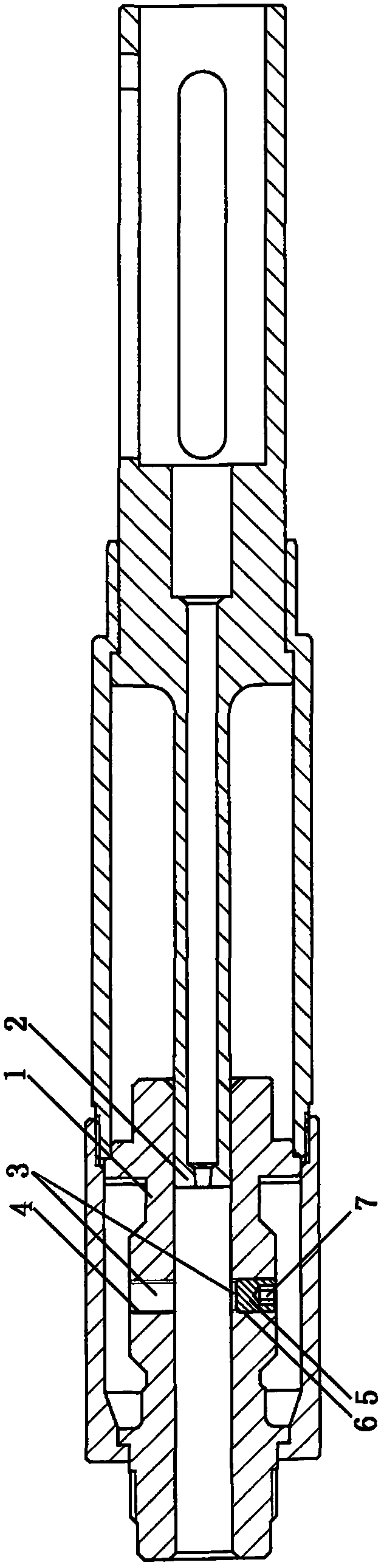
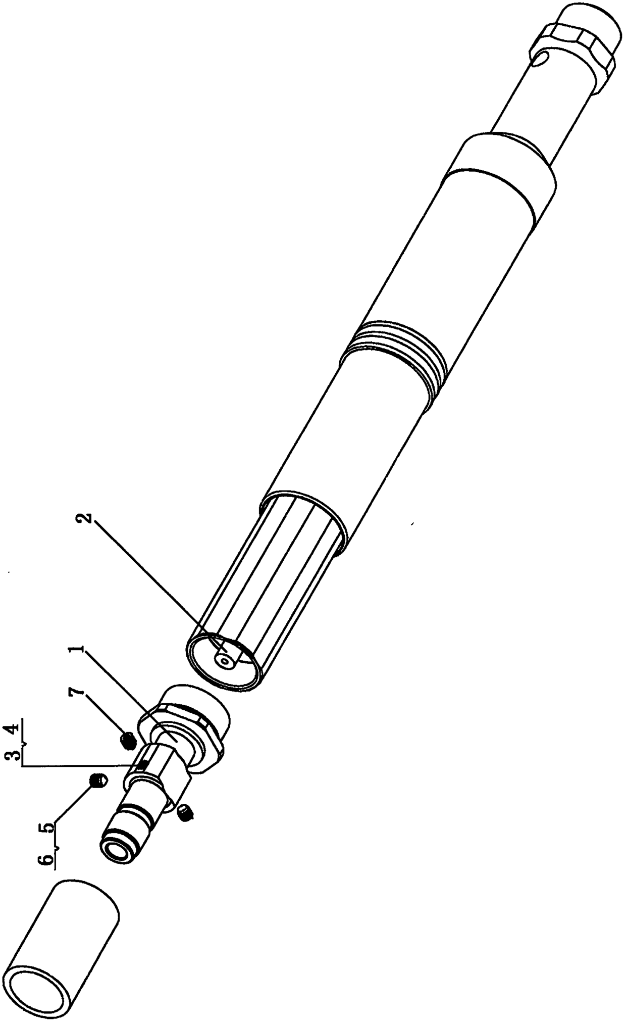
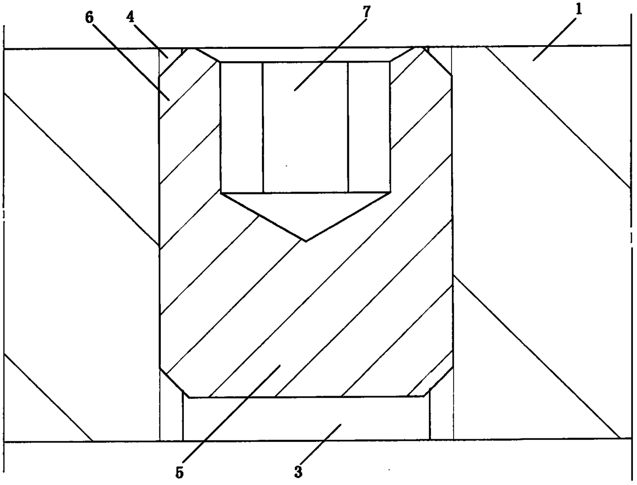
[0027] like figure 1 , figure 2 , image 3 As shown, 1 is a nail tube, 2 is a firing pin cannula, 3 is a pressure relief through hole, 4 is an internal thread, 5 is a cylinder, 6 is an external thread, and 7 is an inner hexagonal concave hole.
[0028] A number of pressure relief through holes 3 are arranged on the wall of the nail tube 1 , and each pressure relief through hole 3 is blocked by a cylinder 5 . The inner thread 4 can be screwed into place.
[0029] At this time, the integrated nail-shooting projectile explodes in the nail tube 1, and since there is no pressure relief through hole 3 connected to the outside, it is in a state of full power operation at this time.
[0030] When the base of the operation is relatively soft, it is necessary to adjust the power to a smaller extent. It is only necessary to disassemble the peripheral components, and then unscrew the cylinder 5 from part of the pressure relief through hole 3 as required. This part of the pressure reli...
Embodiment 2
[0034] like Figure 4 As shown, 8 is a large hole, 9 is a small hole, 10 is the bottom surface of the cylinder, and 11 is a step.
[0035] In actual use, the cylinder 5 cannot penetrate into the interior of the nail tube 1, so as not to hinder the process of nailing, firing and shell removal. In order to achieve the limit, the pressure relief through hole 3 is set to be large on the outside and small on the inside. A step 11 is formed between the large hole 8 and the small hole 9, and only the inner thread 4 is provided on the inner wall of the large hole 8, and the inner wall of the small hole 9 may not be provided with threads, so that the step 11 can screw the screwed cylinder 5. a limit. In addition, in the blocked state, the cylindrical bottom surface 10 and the steps can also have a surface sealing effect, and with the screw seal, a better sealing effect can be achieved.
[0036] In the actual use process of this embodiment, when the large hole 8 is blocked by the cyli...
Embodiment 3
[0038] like Image 6 As shown, 12 is a major path, 13 is a minor path, and 14 is a step.
[0039] The purpose of Example 2 is the same, and it is still to achieve the limit of the cylinder 5, but the limit method is different: the pressure relief through hole 3 is still a stepped hole structure with a large outer and a small inner, and the inner wall of the large hole 8 may not be provided with threads. , The inner wall of the small hole 9 is provided with an internal thread 4;
[0040] When the cylinder 5 is screwed in using the tooling, the external thread 6 outside the small diameter 13 cooperates with the internal thread 4 on the inner wall of the small hole 9 , and the step 11 can limit the step 14 , thereby realizing the limiting of the cylinder 5 . Likewise, step 11 and step 14 can also achieve face sealing.
PUM
 Abstract
Description
Claims
Application Information
 - R&D
- Intellectual Property
- Life Sciences
- Materials
- Tech Scout
- Unparalleled Data Quality
- Higher Quality Content
- 60% Fewer Hallucinations
Browse by: Latest US Patents, China's latest patents, Technical Efficacy Thesaurus, Application Domain, Technology Topic, Popular Technical Reports.
© 2025 PatSnap. All rights reserved.Legal|Privacy policy|Modern Slavery Act Transparency Statement|Sitemap|About US| Contact US: help@patsnap.com