
Glue wiping device

A technology of wiping glue device and tape, applied in the direction of spraying device, etc., can solve the problems of inability to wipe glue, deformation of needle head, inconvenient control of rotating shaft movement, etc., and achieve the effect of not easy to deform and uniform force

Pending Publication Date: 2019-01-11
SHENZHEN JT AUTOMATION EQUIP CO LTD
View PDF0 Cites 2 Cited by
  • Summary
  • Abstract
  • Description
  • Claims
  • Application Information

AI Technical Summary

Problems solved by technology

On the one hand, the movement of the rotating shaft is inconvenient to control, and it is easy to cause deformation of the needle; on the other hand, because the rotating shaft itself has a certain shaft diameter, the glue wiping device cannot wipe glue on short needles.

Method used


Image

  • Glue wiping device
  • Glue wiping device
  • Glue wiping device

Examples


Embodiment Construction

[0030] The following will clearly and completely describe the technical solutions in the embodiments of the present invention with reference to the accompanying drawings in the embodiments of the present invention. Obviously, the described embodiments are only some, not all, embodiments of the present invention. Based on the embodiments of the present invention, all other embodiments obtained by persons of ordinary skill in the art without making creative efforts belong to the protection scope of the present invention.

[0031] The core of the present invention is to provide a glue wiping device, which can wipe off the glue on the short needle, and at the same time, it is not easy to cause deformation of the needle during operation.

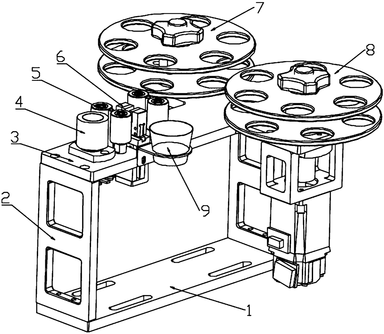
[0032] Please refer to Figure 1-7 , figure 1 Schematic diagram of the structure of the glue wiping device provided by the present invention; figure 2 for figure 1 top view of image 3 A schematic structural view of the clamping assembly pro...


PUM


Abstract

The invention discloses a glue wiping device comprising two clamping faces capable of being matched to clamp a to-be-glue-wiped needle. Glue wiping strips for wiping glue off are arranged between thetwo clamping faces and are in one-to-one correspondence with the clamping faces. The glue wiping device further comprises a driving part which is used for controlling the clamping faces to move so that the glue wiping strips can be attached. According to the glue wiping device provided by the invention, the needle is clamped between the glue wiping strips through the clamping faces, the acting force of the clamping faces to the needle is even, and the needle is not liable to deformation; and the glue wiping strips can wrap the needle completely, and thus the glue wiping device is suitable forthe short needle and high-viscosity glue.

Description

technical field [0001] The invention relates to the technical field of needle type glue dispensing equipment, and more specifically, relates to a glue wiping device. Background technique [0002] The glue wiping device is an important component of needle dispensing equipment, and its main function is to remove the residual glue on the end surface and side of the needle. The gluing device in the prior art includes a set of clamping mechanisms capable of rectilinear movement in opposite directions, and two rotating shafts are installed on the clamping mechanisms. During the working process, the two rotating shafts move towards each other under the control of the clamping mechanism and clamp the needle, then continue to rotate and move along the axial direction of the needle to realize the erasure of glue. [0003] However, when wiping the glue with the above method, it is necessary to control the two rotating shafts to be in a clamped state, and the contact point during the r...

Claims


Application Information

Patent Timeline
IPC IPC(8): B05B15/50
CPCB05B15/50
Inventor 莫曜熙
Owner SHENZHEN JT AUTOMATION EQUIP CO LTD
Learn More