A hemodialyzer and a production method thereof

A technology of hemodialysis and production method, applied in the field of medical devices, can solve the problems of undetectable dialysis membrane, undetectable sealing ring leakage, patient damage, etc., and achieve the effect of avoiding the risk of missing sealing ring

Pending Publication Date: 2019-01-11
徐宏
View PDF0 Cites 0 Cited by
  • Summary
  • Abstract
  • Description
  • Claims
  • Application Information

AI Technical Summary

Problems solved by technology

In the production process of hemodialyzers, the process of assembling the sealing ring and the end cap is generally included, which leads to the risk of missing the sealing ring. If the sealing ring is missing, the patient's blood will flow from the end cap to the Extensive leakage between shells, causing great damage to the patient
[0004] In the prior art, there is also a process of leak detection of the dialysis membrane, but this process is carried out without an end cap installed, so this process cannot detect whether the sealing ring is missing
If the dialysis membrane is tested for leaks when the end cap is installed, part of the end of the dialysis membrane is covered by the sealing ring, and this part of the dialysis membrane cannot be detected. If the position of the sealing ring has been moved during use, blood will enter the In undetected dialysis membranes, there is also a risk of bleeding

Method used


Image

  • A hemodialyzer and a production method thereof
  • A hemodialyzer and a production method thereof
  • A hemodialyzer and a production method thereof

Examples


Embodiment 1

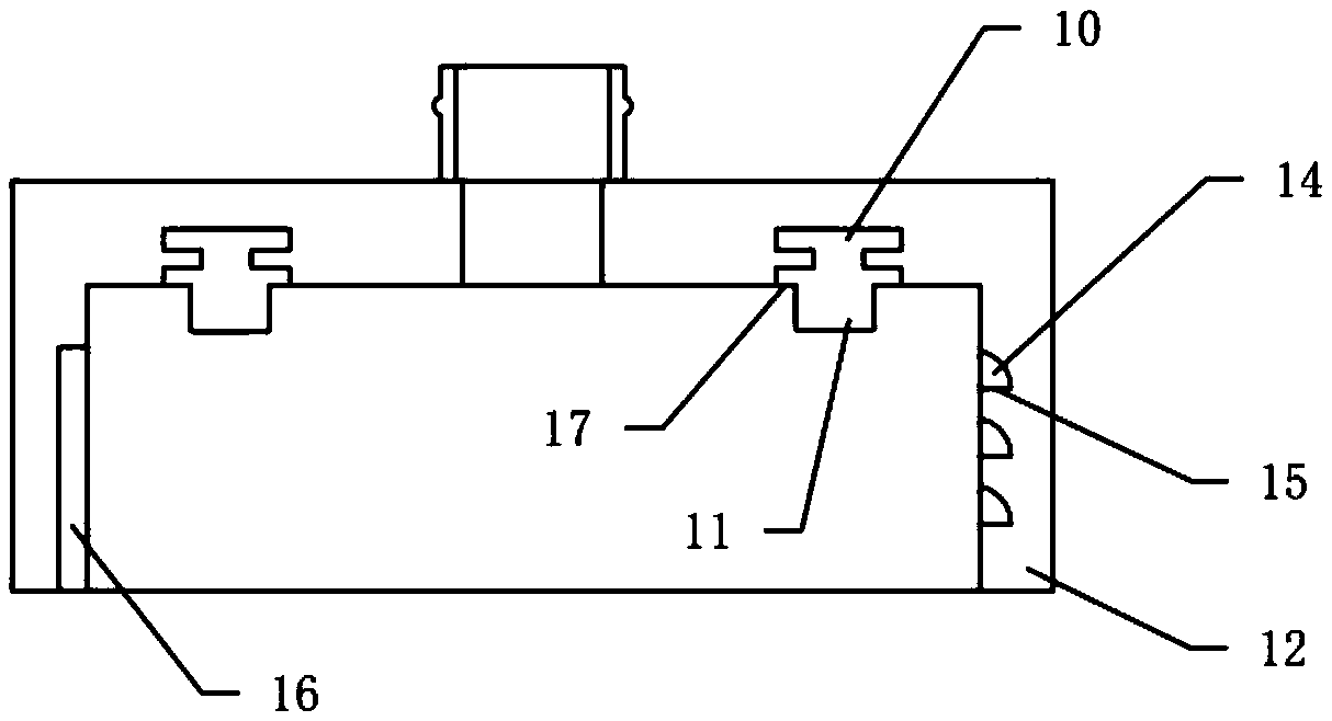
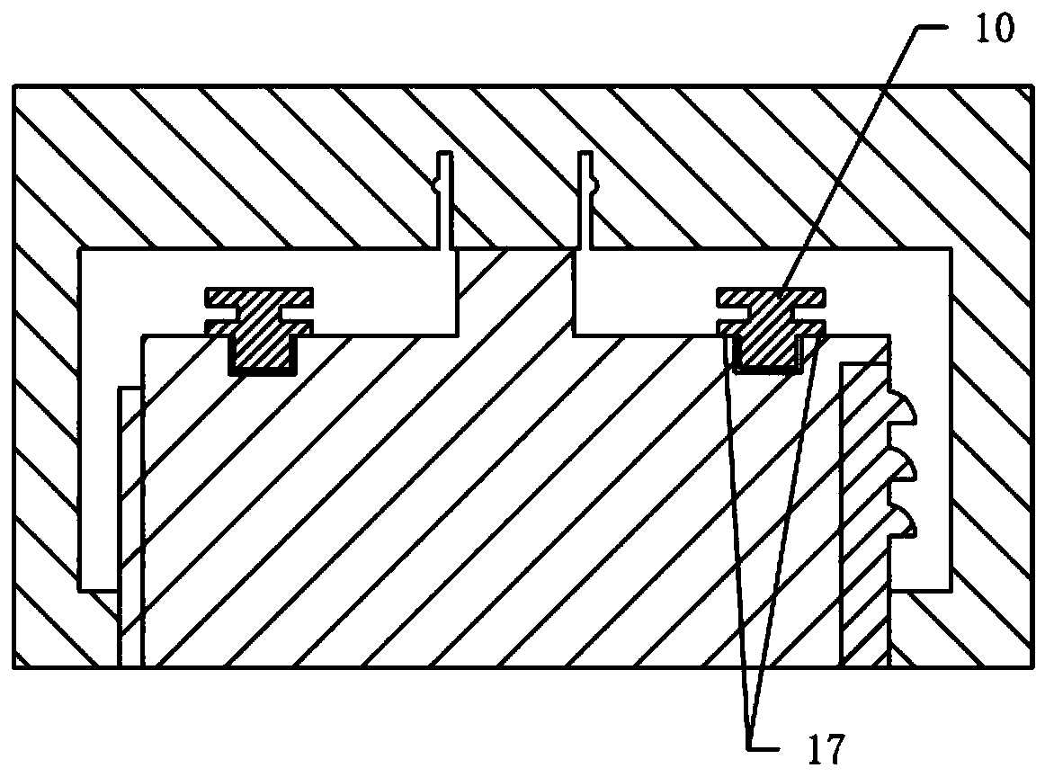
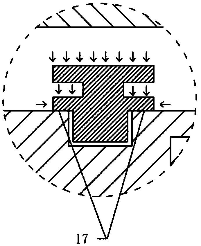
[0042] refer to Figure 1 to Figure 3 ,as well as Figure 7 to Figure 10 , which is Embodiment 1 of the present invention, specifically:

[0043]A hemodialyzer, comprising an end cover, the end cover includes a sealing ring and a cover body 12, a groove is arranged on the inner side of the cover body 12, the sealing ring includes a mounting part 10 and is connected with the mounting part 12. The sealing part 11 connected with the part 10, the mounting part 10 is set in the groove, the sealing part 11 protrudes out of the groove, and the sealing ring and the cover body 12 are in-molded and injected Integral molding, the installation part 10 is "I" type, the installation part 10 is provided with a connection plane 17, the sealing part 11 is connected with the connection plane 17, and the connection plane 17 is connected with the cover 12 are flush on the inner side.

[0044] In this embodiment, the groove is disposed on the top of the inner surface of the cover body 12 , and ...

Embodiment 2

[0065] refer to Figure 4 , Figure 5 , Figure 6 , which is the second embodiment of the present invention, specifically:

[0066] The difference from Embodiment 1 is that the groove is provided on the side wall of the inner surface of the cover body 12, the sealing part 11 is connected to the inner surface of the mounting part 10, and correspondingly, the connection plane 17 is also provided on the inner surface of the sealing part 11 . This embodiment is consistent with the effect achieved by the first embodiment.


PUM


Abstract

A hemodialyzer includes an end cap, which comprises a sealing ring and a cover body, a ring of groove is arranged on the inner side of the cover body, the sealing ring comprises a mounting part and asealing part connected with the mounting part, wherein the mounting part is arranged in the groove, the sealing part protrudes out of the groove, the sealing ring and the cover body are integrally molded by in-mold insert injection molding, the mounting part is of an I type, a connecting plane is arranged on the mounting part, the sealing part is connected with the connecting plane, and the connecting plane is flush with the inner side surface of the cover body. By adopting the structure of the invention, the risk of missing the sealing ring can be avoided; moreover, the in-mold insert injection molding can play a role in error prevention, and the in-mold insert injection molding also has the advantage of low cost; since the sealing ring is installed when the end cover is produced, the sealing ring can be checked in a plurality of subsequent operation steps, and the sealing ring has the function of further error prevention; the invention also has the advantage that the joint of the sealing ring and the end cover is not liable to generate flash.

Description

technical field [0001] The invention relates to the field of medical devices, in particular to a hemodialyzer and a production method thereof. Background technique [0002] The hemodialyzer is a medical consumable for patients with renal failure to undergo dialysis treatment. The hemodialyzer includes a housing and end caps at both ends of the housing. The end caps at both ends of the housing are respectively provided with a blood inlet and a blood outlet. The side of the housing There are dialysate inlet and dialysate outlet on the top near the two ends, and a bunch of dialysis membranes are arranged in the housing. The dialysis membranes of each unit are in the shape of hollow fibers, and the dialysis membranes and the housing are connected by viscose. The two dialysis membranes are also connected by viscose, and the viscose is arranged at the two ends inside the housing. The glue separates the space in the housing from the space in the dialysis membrane, and the two ends ...

Claims


Application Information

Patent Timeline
Patent Type & Authority Applications(China)
IPC IPC(8): A61M1/18
CPCA61M1/1621A61M2207/00A61M2207/10
Inventor 徐宏
Owner 徐宏
Why Eureka
Try Eureka