Performance detection system of electric automobile hub motor

A technology for in-wheel motors and electric vehicles, which is applied in motor-generator testing, electrical measurement, and measurement devices, etc., can solve problems such as hindering the optimization and improvement of in-wheel motor technology, low accuracy of performance test data, and potential safety hazards, and achieves easy promotion, Good fixed, easy to operate effect

Pending Publication Date: 2019-01-08
EAST CHINA JIAOTONG UNIVERSITY
View PDF2 Cites 1 Cited by
  • Summary
  • Abstract
  • Description
  • Claims
  • Application Information

AI Technical Summary

Problems solved by technology

At this stage, most of the performance testing and debugging of in-wheel motor electric wheel drive devices adopt the traditional test method, which is to install the in-wheel motor on the electric vehicle for actual measurement. This method is extremely inefficient and has great safety Hidden danger
In addition, since in-wheel motor-driven electric vehicles have not yet been widely promoted, the existing in-wheel motor test bench technology is not mature enough, and the few simulating load devices for electric vehicle in-wheel motors on the market only consider a single vertical load Loading, such as patents CN201521064909.X and CN201420154405.6, only consider the loading of the vertical load of the hub motor, while the load distribution of the electric vehicle during actual operation is multi-directional, and only consider the vertical load of the electric vehicle hub The motor simulation load device cannot fully reflect the actual working conditions of electric vehicles, so the accuracy of its performance test data is low, which has great potential safety hazards and seriously hinders the further optimization and improvement of in-wheel motor technology in electric vehicles

Method used


Image

  • Performance detection system of electric automobile hub motor
  • Performance detection system of electric automobile hub motor
  • Performance detection system of electric automobile hub motor

Examples


Embodiment Construction

[0039] The patent of the present invention will be further specifically described below in conjunction with the accompanying drawings.

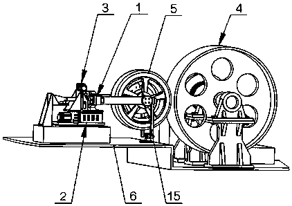
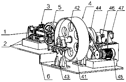
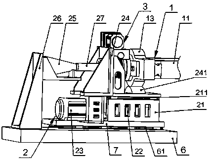
[0040] like Figure 1-4 As shown, a performance detection system for an electric vehicle hub motor includes a wheel connecting frame mechanism 1, a vertical loading mechanism 2, a lateral loading mechanism 3 and a drum dynamometer mechanism 4;

[0041] One end of the wheel connecting frame mechanism 1 is fixedly connected to the wheel 5, and the vertical loading mechanism 2 and the lateral loading mechanism 3 are connected to the other end of the wheel connecting frame mechanism 1;

[0042] The vertical loading mechanism 2 is used to drive the wheel fixing frame mechanism 1 and vertically load the wheels 5;

[0043] The lateral loading mechanism 3 is used to drive the wheel fixing frame mechanism 1 and laterally load the wheels 5;

[0044] The drum 41 of the drum dynamometer 4 is in contact with the wheel 5 , and the drum dynamometer 4 can ...


PUM


Abstract

The invention relates to a performance detection system of an electric automobile hub motor. The system comprises a wheel connecting frame mechanism, a vertical loading mechanism, a lateral loading mechanism and a roller dynamometer mechanism; one end of the wheel connecting frame mechanism is fixedly connected with a wheel; the vertical loading mechanism and the lateral loading mechanism are bothconnected with the other end of the wheel connecting frame mechanism; the vertical loading mechanism is used for driving the wheel fixing frame mechanism and carrying out vertical loading on the wheel; the lateral loading mechanism is used for driving the wheel fixing frame mechanism and carrying out lateral loading on the wheel; a roller of the roller dynamometer mechanism is in contact fit withthe wheel; and the roller dynamometer mechanism can detect running data of the wheel. The vertical loading mechanism can carry out vertical loading on the wheel, the lateral loading mechanism can carry out lateral loading on the wheel, and the roller dynamometer mechanism can detect the running data of the wheel, so that a more detailed load simulation test can be performed for the hub motor; andthe system is high in precision, convenient to operate and easy to popularize.

Description

technical field [0001] The invention relates to a performance detection system of a hub motor, in particular to a performance detection system of an electric vehicle hub motor. Background technique [0002] Facing the increasingly severe energy crisis and environmental pollution, countries around the world have successively announced the time to ban the sale of fuel vehicles, and the development of new energy vehicles has become an irresistible trend. As the mainstream of new energy vehicle development, electric vehicles have made great progress. The driving method of driving electric vehicles with in-wheel motors is called the final driving mode of future electric vehicles and has broad market prospects. [0003] The safety and reliability of electric vehicles are very important performance indicators, so the performance test of the hub motor is an essential work. At present, there are many test devices for traditional vehicles on the market, but there are very few test b...

Claims


Application Information

Patent Timeline
IPC IPC(8): G01R31/34
CPCG01R31/006G01R31/343
Inventor 陈齐平罗群黄娟林
Owner EAST CHINA JIAOTONG UNIVERSITY
Why Eureka
Try Eureka