
Plastic mold inclined roof structure with sliding block

A plastic mold and lifter technology, which is applied in the field of advanced manufacturing and automation, can solve the problems of complex parts structure, increase the size of the lifter, and need to replace parts, etc., to achieve the effect of low application cost, prevention of movement overrun, and improvement of yield.

Active Publication Date: 2019-01-04
杜弗尼工程机械(苏州)有限公司
View PDF8 Cites 0 Cited by
  • Summary
  • Abstract
  • Description
  • Claims
  • Application Information

AI Technical Summary

Problems solved by technology

[0008] Purpose of the invention: The purpose of the present invention is to provide a plastic mold slanted roof structure with sliders, to solve the undercut in the moving direction of the slanted roof, it is necessary to adopt a complex structure to prevent the product from being strained. In such a plastic mold, the size of the slanted roof is increased, occupying Space, and the structure of the parts is complex, the cost is also high, and there are often problems such as replacement of parts during the life cycle of the mold

Method used


Image

  • Plastic mold inclined roof structure with sliding block
  • Plastic mold inclined roof structure with sliding block
  • Plastic mold inclined roof structure with sliding block

Examples


Embodiment

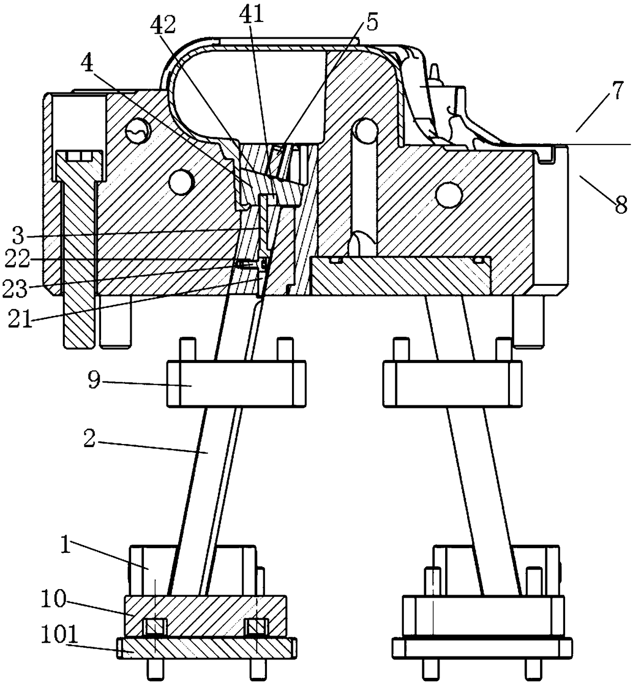
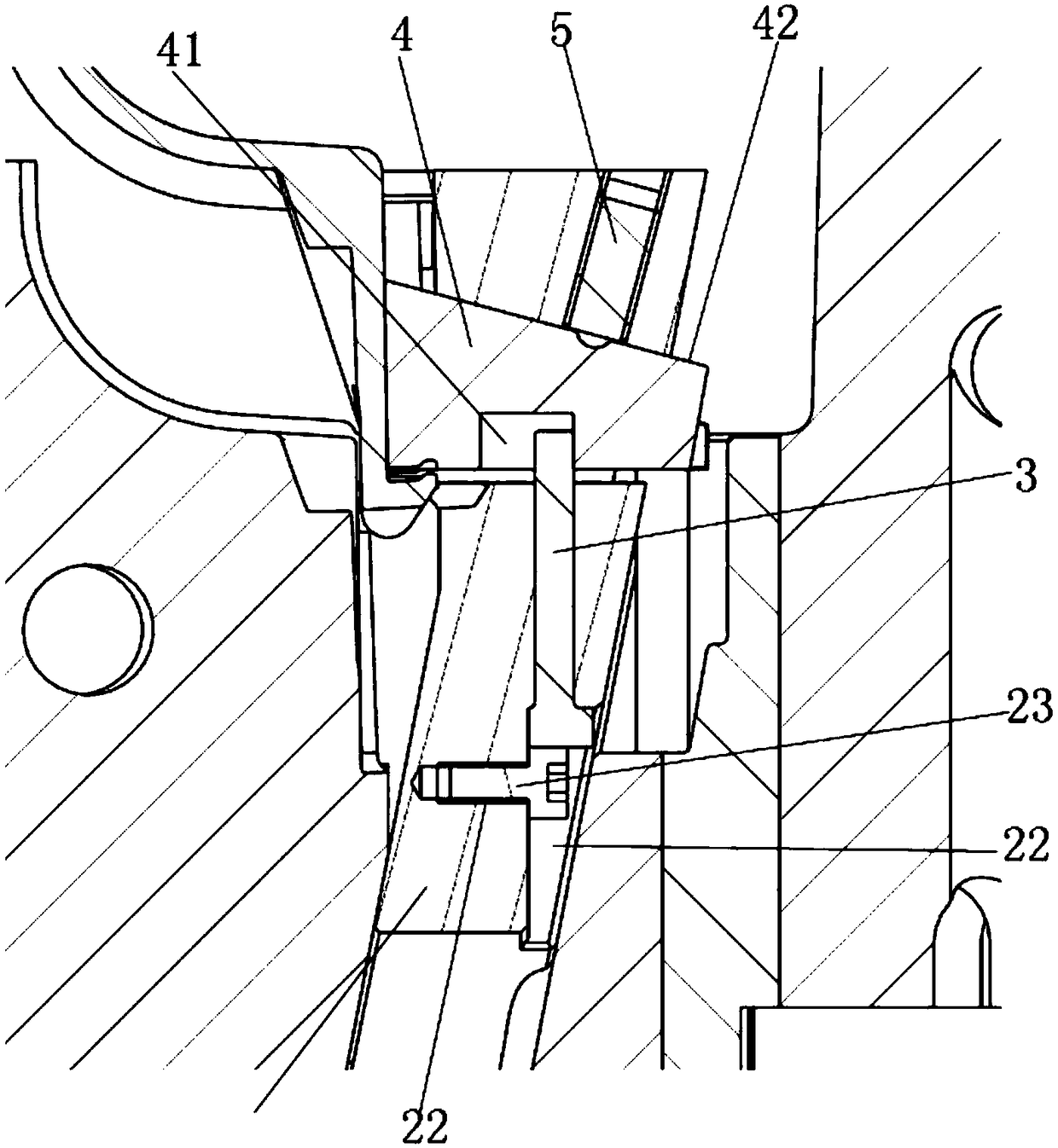
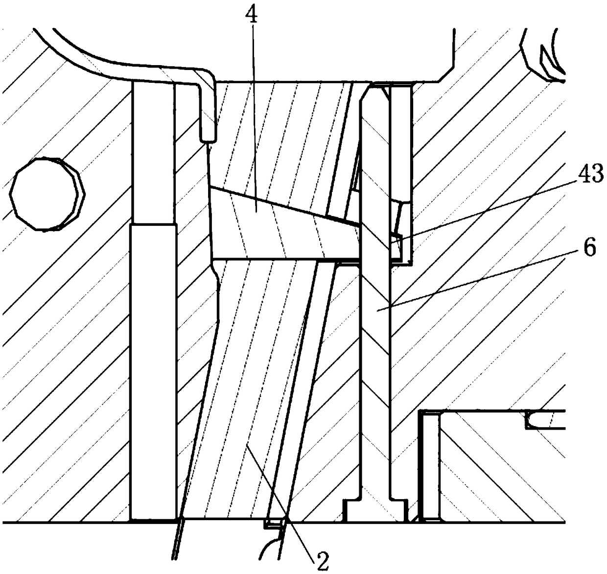
[0033] Such as Figure 1-3The inclined roof structure of the plastic mold with the slider shown includes the inclined roof seat 1, the inclined roof 2, the inner slider bar 3, the inner slider 4 of the inclined roof, the inner slider positioning ball screw 5, and the vertical guide rod 6. On the fixed mold side 7 and the movable mold side 8, the inclined roof 2 is arranged obliquely. The end faces are fitted together, the lower end surface of the inner slider 4 of the inclined roof is provided with a first groove 41, the inner slider bar 3 is arranged in the inclined roof 2, and the upper end of the inner slider bar 3 is arranged on In the first groove 41, the inner slider positioning ball screw 5 is arranged on the fixed mold side 7, and the lower end of the inner slider positioning ball screw 5 is attached to the upper end surface of the inclined top inner slider 4, The vertical guide rod 6 is vertically arranged in the movable mold side 8, and the vertical guide rod 6 runs...


PUM


Abstract

The invention discloses a plastic mold inclined roof structure with a sliding block, and belongs to the field of advanced manufacturing and automation. The structure includes an inclined roof seat, aninclined roof, an inner sliding block lever, an inclined roof inner sliding block, an inner sliding block positioning wave bead screw, a vertical guide rod, a fixed mold side and a movable mold side,a first groove is formed in the lower end surface of the inclined roof inner sliding block, the inner sliding block lever is disposed in the inclined roof, the upper end portion of the inner slidingblock lever is disposed In the first groove, the inner sliding positioning bead screw is disposed on the fixed mold side, the lower end portion of the inner sliding positioning bead screw fits the upper end surface of the inclined roof inner sliding block, the vertical guide rod is vertically disposed within the movable mold side, and the vertical guide rod penetrates through the inclined roof inner sliding block. The structure can ensure that a mold does not pull a product and the finished product rate is improved when the mold is pulled out and turned upside down by setting the vertical guide rod in the mold; the inner sliding block lever can be set to limit the inclined roof inner sliding block to prevent the inclined roof inner sliding block from moving down beyond a specified distanceand crushing the product.

Description

technical field [0001] The invention belongs to the field of advanced manufacturing and automation, and in particular relates to a plastic mold inclined roof structure with a slider. Background technique [0002] The structure of the inclined top is often used in plastic molds. When there is an undercut along the moving direction of the inclined top, the inclined top will strain the product or even the inclined top cannot be ejected. The usual solution is to move the slider vertically. Arrangement of core-pulling or inclined top mechanism, but the use of the above two mechanisms has the following problems: [0003] 1. The core-pulling mechanism needs to be driven by an oil cylinder. The oil cylinder needs to be embedded inside the core, and a large amount of steel needs to be removed from the core, which seriously affects the strength of the mold; [0004] 2. Adopt the sliding block downward inclined roof mechanism, if the operation is wrong, it will easily cause the slidin...

Claims


Application Information

Patent Timeline
IPC IPC(8): B29C45/40B29C45/33
CPCB29C45/332B29C45/4005
Inventor 黄裕江陈泓吉
Owner 杜弗尼工程机械(苏州)有限公司
Learn More