


Quick Research
Generate reliable direction feasibility study reports for your R&D in just a few steps.

Technical Q&A
Discover and master advanced knowledge NOW. Basics, ideas, possibilities, all at once.

Find Solutions
As an expert in R&D theories, this can generate solutions to your technical problems instantly.

Evaluate Feasibility
Analyze your overall solution with one click, know your potential R&D risks in advance.

Monitor Landscape
Get weekly tech updates, stay abreast of the latest tech innovations and key insights.
Method, device and system for concurrent wireless voice transmission
A technology for wireless voice and voice data, applied in radio transmission systems, transmission systems, diversity/multi-antenna systems, etc. The effect of a large number of concurrent and stable voice data transmission
- Summary
- Abstract
- Description
- Claims
- Application Information
AI Technical Summary
Problems solved by technology
Method used
Image

Examples
Embodiment 1
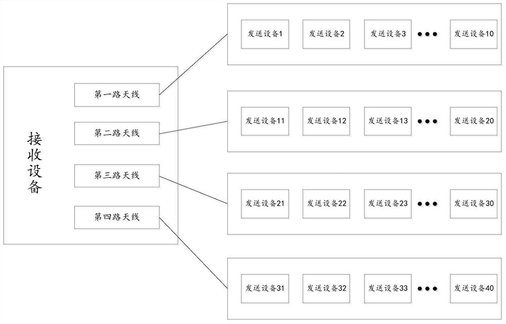
[0052] see figure 1 , figure 1 is a schematic diagram of an application scenario provided by an embodiment of the present invention;
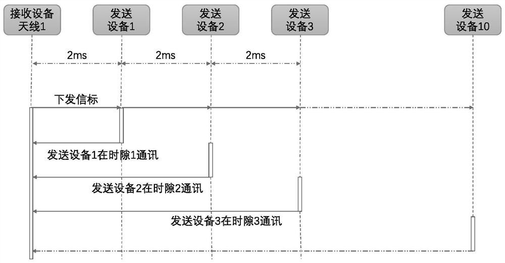
[0053] Such as figure 1 As shown, the receiving device includes multiple antennas, where, figure 1 Taking four antennas as an example for illustration, it can be understood that each antenna corresponds to the same number of sending devices, and the wireless communication address of each antenna is unique. Among them, each antenna corresponds to 10 sending devices, and each sending device corresponds to a unique device serial number. Specifically, the first antenna corresponds to a sending device with a device serial number of 1-10, and the second antenna corresponds to a device with a serial number of 11. -20 sending device, the third antenna corresponds to the sending device whose device serial number is 21-30, and the fourth antenna corresponds to the sending device whose device serial number is 31-40, and each sending device sends a voic...
Embodiment 2
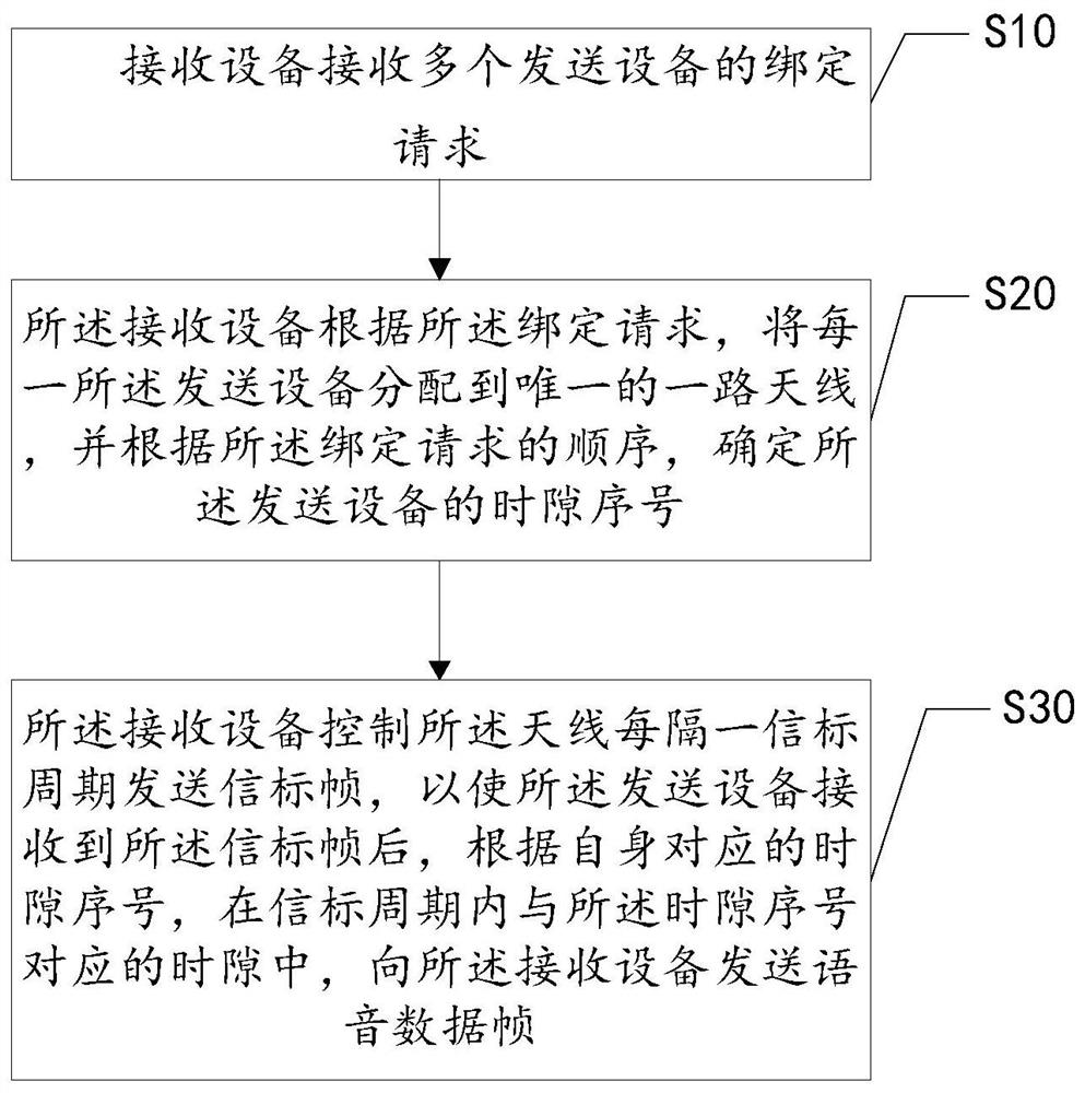
[0078] see Figure 7 , Figure 7 It is a schematic diagram of an apparatus for concurrent wireless voice transmission provided by an embodiment of the present invention. The apparatus for concurrent wireless voice transmission can be applied to a receiving device, such as Figure 7 As shown, the device 70 for concurrent wireless voice transmission includes:
[0079] A binding request unit 71, configured for the receiving device to receive binding requests from multiple sending devices;
[0080] The time slot sequence number unit 72 is used for the receiving device to assign each of the sending devices to a unique antenna according to the binding request, and determine the timing of the sending device according to the order of the binding requests. slot number;
[0081] The beacon frame sending unit 73 is used for the receiving device to control the antenna to send a beacon frame every other beacon period, so that after the sending device receives the beacon frame, it , sen...
PUM
 Abstract
Description
Claims
Application Information
 - R&D Engineer
- R&D Manager
- IP Professional
- Industry Leading Data Capabilities
- Powerful AI technology
- Patent DNA Extraction
Browse by: Latest US Patents, China's latest patents, Technical Efficacy Thesaurus, Application Domain, Technology Topic, Popular Technical Reports.
© 2024 PatSnap. All rights reserved.Legal|Privacy policy|Modern Slavery Act Transparency Statement|Sitemap|About US| Contact US: help@patsnap.com