
Oil scraping device of petroleum engineering oil production well and using method thereof

A technology of oil scraping device and petroleum engineering, which is used in earth-moving drilling, wellbore/well components, cleaning appliances, etc., can solve the problems of fixed block not being pushed, no buffer device or return action mechanism, caking, etc. Achieve the effect of improving mud scraping efficiency and overcoming motor lockup

Inactive Publication Date: 2019-01-01
李如平
View PDF12 Cites 3 Cited by
  • Summary
  • Abstract
  • Description
  • Claims
  • Application Information

AI Technical Summary

Problems solved by technology

This kind of oil scraping device will have many problems in actual use. For example, when the sediment is blocked in the oil production pipe, agglomeration may occur. The agglomeration is relatively hard, and the adhesion with the oil production pipe is relatively strong. The block may not be able to be pushed, and there is no buffer device or return action mechanism. If the condition is serious, the motor may be damaged

Method used


Image

  • Oil scraping device of petroleum engineering oil production well and using method thereof
  • Oil scraping device of petroleum engineering oil production well and using method thereof
  • Oil scraping device of petroleum engineering oil production well and using method thereof

Examples


Embodiment 1

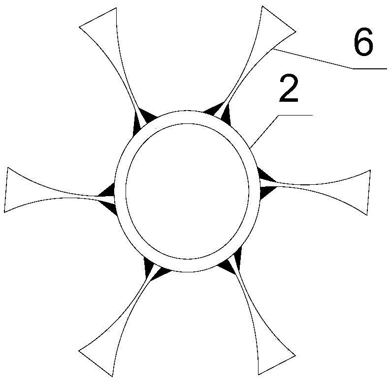
[0034] Such as image 3 As shown, the side ends of the blades 6 have blades. The blade 6 is in the form of a hyperboloid, forming a two-way blade at the outer end of the page. The blade 6 is a metal plate. The material of the blade 6 is stainless steel. It is vertically connected to the outer wall of the blade rotor. The included angle between two adjacent blades is the same.

Embodiment 2

[0036] Such as Figure 4 As shown, the page has blades on both the lower end face and the side end faces. Blade 6 is a shuttle-shaped surface, forming a blade at the end, which is conducive to scraping silt. The blade 6 is welded to the blade rotating rod, and the welding place is provided with reinforcing ribs. The design of the ribs can greatly improve the shear resistance of the blade 6 . The reinforcing rib can be a wedge-shaped metal block, which is welded between the blade 6 and the blade rotating rod 2, and directly fills the gap formed between the three. The purpose of this design is that it is easy to handle later. Although the gravity of the mud scraping device is increased, in actual operation, the increased gravity is more conducive to the rotation of the blades.

Embodiment 3

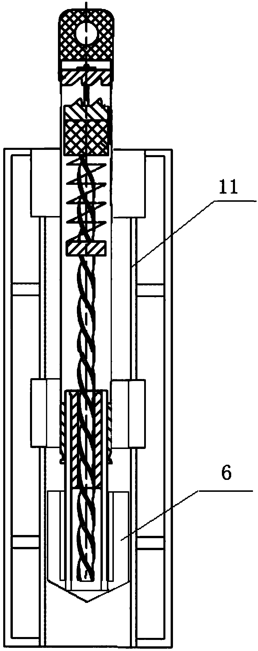
[0038] Such as Figure 5 Shown is a schematic structural view of the blade 6 . The pages have knives on both the lower end face and the side end faces. Blade 6 is a shuttle-shaped surface, forming a blade at the end, which is conducive to scraping silt. The blade 6 is welded to the blade rotating rod, and the welding place is provided with reinforcing ribs. The blade 6 can be designed to have a tip at the bottom, so that the plane shape of a single blade is trapezoidal or conical. For harder silt, it has a certain penetrating power and opens a passage for the blade 6 to enter the hard silt. Moreover, the side end surface of the blade 6 also has a blade portion, which makes the silt fall off rapidly under high-speed rotation after scraping the silt.

[0039] In the blade structures shown in Embodiment 1 and Embodiment 2, the bottom of the blade 6 can also be designed as a pointed portion, so as to further improve the working efficiency of scraping mud.

[0040] In order to ...


PUM


Abstract

The invention discloses an oil scraping device of a petroleum engineering oil production well and a using method thereof. The oil scraping device comprises a top pressing rod, a blade rotating rod, apair of one-way gears which mesh with each other, a screw rod, a transmission part and blades. The top pressing rod and the blade rotating rod are hollow sleeves correspondingly, the lower end of thetop pressing rod is connected with the upper end of the blade rotating rod in a sleeving mode, multiple blades are connected to the outer wall of the lower portion of the blade rotating rod, a certaindistance between the blades and the top pressing rod is provided, and the distance is greater than that of motion of the top pressing rod relative to the blade rotating rod; the pair of one-way gearsare arranged in the top pressing rod in an up-down mode, lower gears are connected with the screw rod, and the screw rod is movably connected into the top pressing rod and extends into the blade rotating rod; and the transmission part is fixedly connected to the blade rotating rod, the transmission part is provided with a threaded hole matched with the screw rod in a threaded mode, and a ball matched with the screw rod is arranged in the transmission part. According to the oil scraping device, the blades are driven to rotate at high speed by the blade rotating rod, and the efficiency of oil scraping is improved.

Description

technical field [0001] The invention belongs to the technical field of petroleum engineering, and in particular relates to an oil scraping device for oil production wells in petroleum engineering and a using method thereof. Background technique [0002] The development and development of the oil scraping device integrates the oil scraping and decontamination function of the oil production pipe oil scraper, which can fundamentally solve the problem caused by sudden steam channeling and blowout during the process of raising and lowering the oil production pipe during thermal recovery, switching down the pump, and pump inspection well. To solve the problem of environmental pollution, this device is widely used in the workover industry, and it is more common in heavy oil blocks in oil fields and domestic heavy oil markets. [0003] In accordance with the requirements of the technical operation standards for workover operations, oil production pipe scrapers must be installed duri...

Claims


Application Information

Patent Timeline
IPC IPC(8): E21B37/02
CPCE21B37/02
Inventor 秦磊磊王义刚崔全义王义震罗海涛赵磊邹京伦刘蕊田科
Owner 李如平
Learn More