Automatic production line for stamping and welding parts
An automatic production line, stamping and welding technology, applied in the field of parts processing, can solve the problems of low production efficiency, achieve the effect of improving production efficiency and perfecting automation
- Summary
- Abstract
- Description
- Claims
- Application Information
AI Technical Summary
Problems solved by technology
Method used
Image

Examples
Embodiment 1
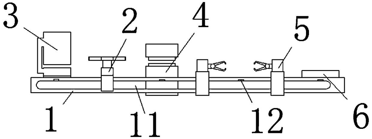
[0024] see figure 1 , this embodiment provides an automatic production line for stamping and welding of parts, including a transmission rail 1, on which a feeding device 3, a punching machine 4, a welding device 5 and a discharge plate are sequentially arranged from left to right 6, and the transmission rail 1 is provided with a clamping device 2, and several inductors 12 are fixed inside the transmission rail 1. Just below.
[0025] In this embodiment, in the operation, the first punching and blanking is completed, and the parts whose shape is determined are placed in the feeding device 3, and the parts are taken out from the feeding device 3 through the clamping device 2, and the parts are passed through the punching machine. 4 and welding device 5 for punching and welding, and finally place the processed parts on the discharge plate 6, use the clamping device 2, cancel the process of manual handling, improve production efficiency, and the entire process is automated to red...
Embodiment 2
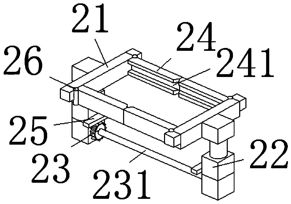
[0028] see figure 1 , figure 2 and Figure 6 , On the basis of Embodiment 1, a further improvement is made: the clamping device 2 includes a clamping block 21, a first lifting rod 22, a gear 23, a clamping claw 24, a limit block 25 and a first rotating shaft 26, and the gear 23 is set There are two, respectively installed on the outside of the two first cavities 11, the two gears 23 are installed on the inside of the first lifting rod 22 for rotation, and the two clamping blocks 21 are respectively fixed on the upper ends of the two first lifting rods 22 The inner side of the clamping claw 24 is provided with four, and two by two are installed on the left and right ends of the two clamping blocks 21 through the rotation of the first rotating shaft 26, and the limit block 25 is arranged on the inner lower end of the first elevating rod 22. The rail 1 is provided with front and rear two, and the first cavity 11 is opened in the transmission rail 1, the inductor 12 is arranged...
Embodiment 3
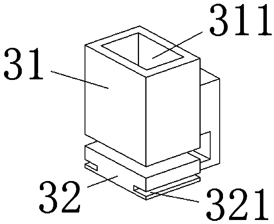
[0035] see image 3 , On the basis of Embodiment 1, a further improvement has been made: the feeding device 3 includes a feeding box 31 and a base 32, the feeding box 31 is fixed on the upper end of the base 32, and the feeding box 31 is provided with a matching plate 211 The material inlet 311 and the left and right ends of the base 32 are provided with a third groove 321 matching with the limit block 25 .
[0036]In this embodiment, the feed box 31 is provided with a feed port 311 matching the fixed plate 211. After the fixed plate 211 completes the blanking and determines the shape parts, it is stored in the feed device 3 through the feed port 311. Falling on the upper end of the base 32, when the clamping device 2 moves to the lower end of the feeding device 3, the clamping block 21 and the clamping claw 24 clamp the fixed plate 211 through the sensor 12 and the processor, and a third The groove 321 avoids interference with the limit block 25, resulting in the failure of ...
PUM
 Abstract
Description
Claims
Application Information
 - R&D
- Intellectual Property
- Life Sciences
- Materials
- Tech Scout
- Unparalleled Data Quality
- Higher Quality Content
- 60% Fewer Hallucinations
Browse by: Latest US Patents, China's latest patents, Technical Efficacy Thesaurus, Application Domain, Technology Topic, Popular Technical Reports.
© 2025 PatSnap. All rights reserved.Legal|Privacy policy|Modern Slavery Act Transparency Statement|Sitemap|About US| Contact US: help@patsnap.com