
Physical horizontal projection motion verification experimental device

An experimental device and a technology of flat throwing, applied in the direction of educational appliances, instruments, teaching models, etc., can solve the problems of large initial height error, poor use effect, verification experiment, etc., achieve intuitive experimental phenomena, good teaching effect, reduce The effect of small errors

Inactive Publication Date: 2018-12-25
胡玥瑶
View PDF6 Cites 7 Cited by
  • Summary
  • Abstract
  • Description
  • Claims
  • Application Information

AI Technical Summary

Problems solved by technology

[0003] The existing physical flat-throw motion verification experimental device has the following defects: when verifying the motion in the horizontal direction of the flat-throw motion, the ball in the flat-throw motion cannot start to move simultaneously with the small ball in a uniform linear motion, and the flat-throw motion The error between the initial velocity of the ball and the speed of the ball moving in a straight line at a uniform speed is relatively large; when verifying the vertical movement of the flat throwing motion, the flat throwing ball cannot start to move at the same time as the free falling ball. In addition, there is a large error between the initial height of the ball in flat throwing motion and the initial height of the ball in free fall; there is no device for simulating the horizontal and vertical movement of the ball at different times, and it is not possible to intuitively pass the ball relative to each other. Colliding to verify the experiment is not easy for students to understand, and the effect of use is not good

Method used


Image

  • Physical horizontal projection motion verification experimental device
  • Physical horizontal projection motion verification experimental device
  • Physical horizontal projection motion verification experimental device

Examples


Embodiment Construction

[0029] The present invention will be further described below in combination with the accompanying drawings and specific embodiments.

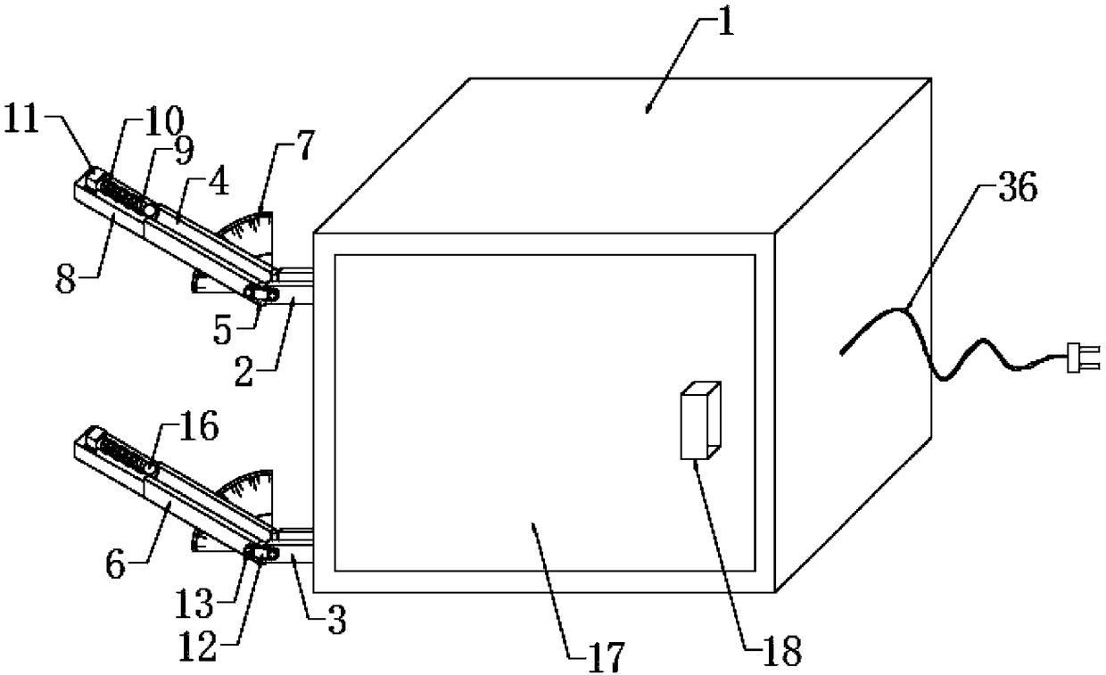
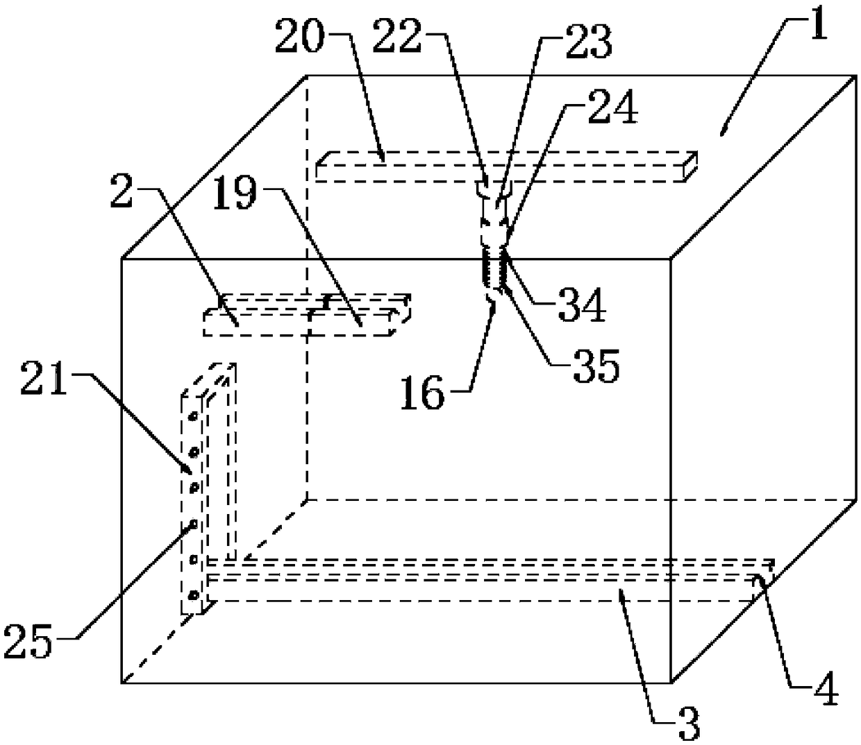
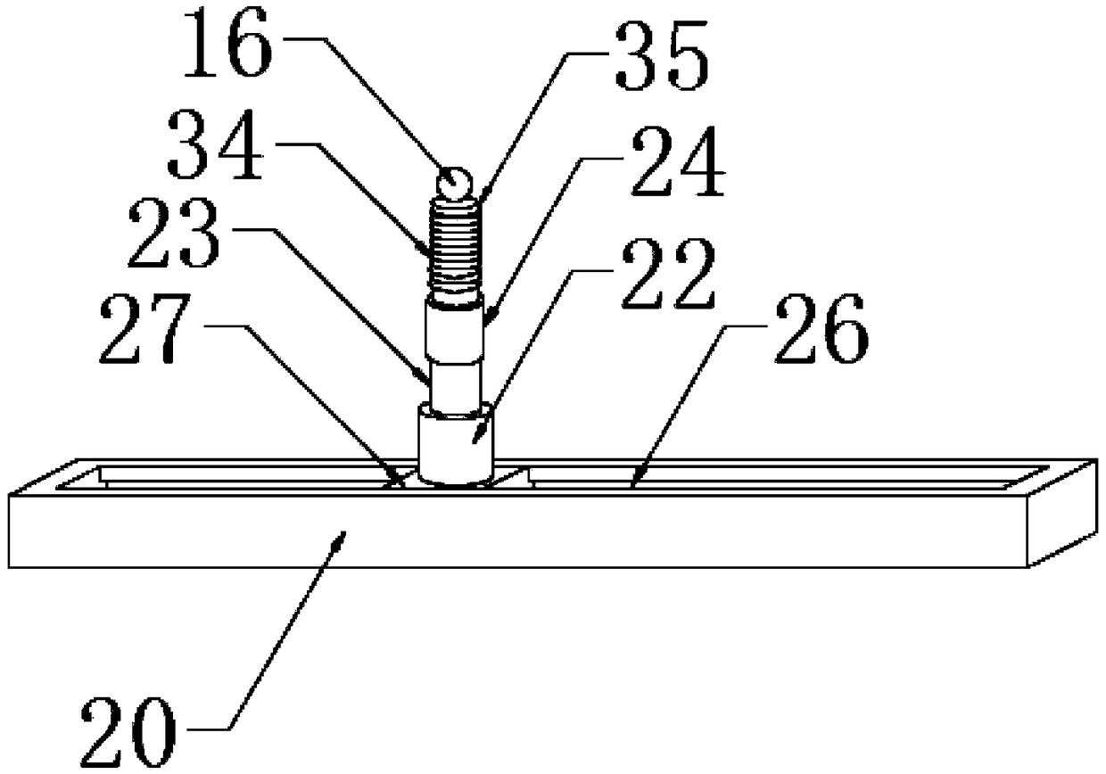
[0030] see Figure 1-10 , the present invention provides a technical solution: a physical flat throwing motion verification experiment device, including an experiment box 1, a first horizontal plate 2 is respectively installed on one side of the experiment box 1, and the first horizontal plate 2 is embedded in the experiment box 1, one side of the first horizontal plate 2 is installed with a movable plate 19, a hinge 31 is installed between the first horizontal plate 2 and the movable plate 19, and the first horizontal plate 2 and the movable plate 19 pass through the hinge 31 Connection, the inside of the movable plate 19 is equipped with a micro switch 32, and the micro switch 32 is embedded in the inside of the movable plate 19, the top of the micro switch 32 is equipped with a transmission piece 33, and one end of the transmission piece 33 ...


PUM


Abstract

The invention provides a physical horizontal projection motion verification experimental device. The physical horizontal projection motion verification experimental device comprises an experimental box; a first horizontal plate is arranged on one side of the experimental box, and the first horizontal plate is embedded in one side of the experimental box; a movable plate is arranged on one side ofthe first horizontal plate; hinges are arranged between the first horizontal plate and the movable plates, and the first horizontal plate and the movable plate are connected through the hinges; and amicro switch is disposed in the movable plate. Horizontal and vertical motion of the horizontal projection motion can be simulated at different times, and the design can greatly reduce errors during the experiment, make an experimental phenomenon more intuitive and a teaching effect better, facilitates understanding of the student, the inclination degree of upper and lower inclined plates can be adjusted by rotating movable bolts to change the initial speed of the small iron ball during the horizontal projection motion to carry out many experiments; the contingency of the experiment can be avoided, and experimental errors can be reduced; and the physical horizontal projection motion verification experimental device is simple to operate, and is high in practicality.

Description

technical field [0001] The invention relates to the technical field of physical experiment devices, in particular to a physical flat throw motion verification experiment device. Background technique [0002] The object is thrown horizontally with a certain initial velocity. If the object is only affected by gravity, this kind of motion is called flat throwing motion. The motion of flat throwing can be regarded as the combined motion of uniform linear motion in the horizontal direction and free fall motion in the vertical direction. The object in flat throwing motion, because the resultant external force it receives is a constant force, so the flat throwing motion is a uniform speed curve motion, and the motion trajectory of the flat throwing object is a parabola. The flat throwing motion is a curved motion. The time of the flat throwing motion is only related to the vertical height of the throwing point; the horizontal displacement of the object on the ground is related to ...

Claims


Application Information

Patent Timeline
IPC IPC(8): G09B23/10
CPCG09B23/10
Inventor 胡玥瑶
Owner 胡玥瑶
Learn More