
Special mobile vehicle for patient suffering from diseases on lower limbs

A technology for patients and mobile vehicles, which can be used in patient chairs or special transportation tools, vehicle ambulance, medical transportation, etc. It can solve the problem of single function, inconvenient disassembly, transfer and adjustment, and the inability to adjust the height of patients with disabled limbs and angles, etc., to achieve the effect of simple structure, convenient riding and disassembly, and reducing hidden dangers

Inactive Publication Date: 2018-11-06
傅捷辉
View PDF10 Cites 0 Cited by
  • Summary
  • Abstract
  • Description
  • Claims
  • Application Information

AI Technical Summary

Problems solved by technology

[0002] Wheelchairs are not only a means of transportation for people with lower limb dysfunction such as amputations, paraplegia, hemiplegia, fractures, and people with walking difficulties such as frailty, but more importantly, they can use wheelchairs to perform physical exercises and participate in social activities. However, existing wheelchairs have simple structures. , the function is single, it only has the function of carrying people, and it cannot lift and fix the disabled limbs of the patient. Secondly, it cannot adjust the appropriate height and angle according to the needs of the disabled limbs of the patient. Furthermore, the existing wheelchair movement method is relatively inconvenient. , it is not convenient to disassemble, transfer and adjust, therefore, we propose a special mobile vehicle for patients with lower limb diseases

Method used


Image

  • Special mobile vehicle for patient suffering from diseases on lower limbs
  • Special mobile vehicle for patient suffering from diseases on lower limbs
  • Special mobile vehicle for patient suffering from diseases on lower limbs

Examples


Embodiment Construction

[0020] In order to make the technical means, creative features, goals and effects achieved by the present invention easy to understand, the present invention will be further described below in conjunction with specific embodiments.

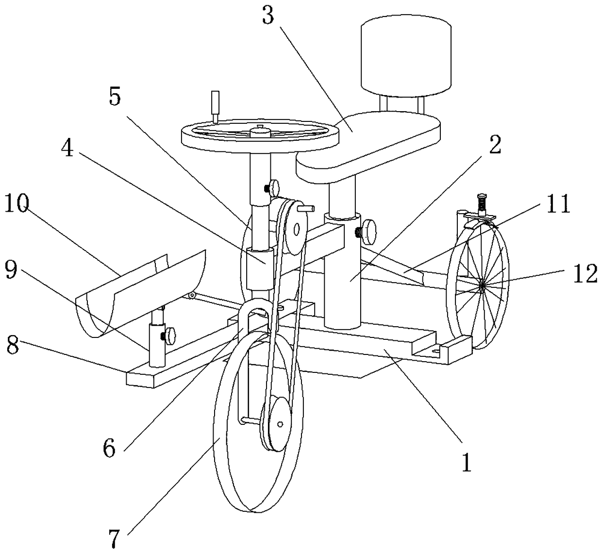
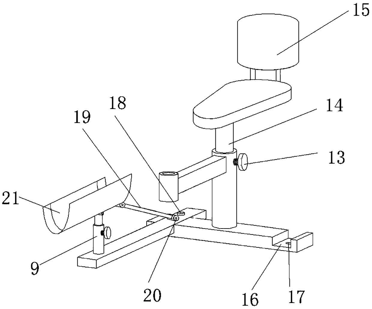
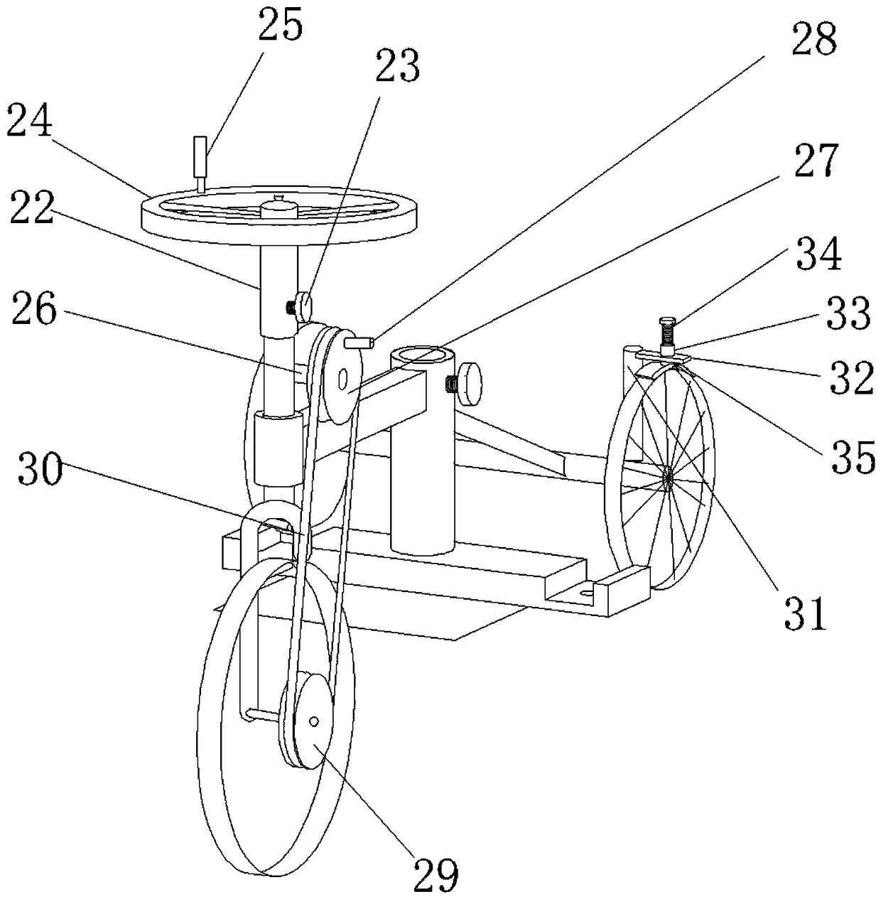
[0021] Such as Figure 1-3 As shown, a special mobile vehicle for patients with lower extremity diseases, including a support base 1, a main support 2, a seat cushion 3, a vehicle frame 4, a steering rod 5, a front fork 6, a front wheel 7, a tripod base 8, and a telescopic support 9 And the tripod 10, the middle part of the upper end of the support base 1 is provided with a main bracket 2, the top of the main bracket 2 is provided with a cushion 3, the front end of the main bracket 2 is provided with a vehicle frame 4, and the front end of the vehicle frame 4 is provided with Direction rod 5, the lower end of the direction rod 5 is provided with a front fork 6, the inner wall of the lower end of the front fork 6 is provided with a front wheel 7, a...


PUM


Abstract

The invention discloses a special mobile vehicle for a patient suffering from diseases on lower limbs. The mobile vehicle comprises a supporting base, a main supporting frame, a seat cushion, a vehicle frame, a steering rod, a front fork, a front wheel, a foot support base, a retractable bracket and a foot support; the main supporting frame is disposed in the middle of the upper end of the supporting base, the seat cushion is disposed on the top of the main supporting frame, the vehicle frame is disposed at the front end of the main supporting frame, the steering rod is disposed at the front end of the vehicle frame, the front fork is disposed at the lower end of the steering rod, the front wheel is arranged on the inner wall of the lower end of the front fork, the foot support base is arranged on the front side of the left end of the supporting base, and the foot support is connected to the upper side of the front end of the foot support base through the arranged retractable bracket.According to the mobile vehicle, through arrangement of the foot support base on the front side of the left end of the supporting base, the retractable bracket on the upper side of the front end of the foot support base and the foot support, convenience is provided for lifting and fixing the disabled limbs of the patient, the height and the angle can be adjusted at the same time, the structure issimple, convenience is provided for riding and disassembly, and the mobile vehicle is practical and suitable for wide application and popularization.

Description

technical field [0001] The invention relates to the field of medical equipment, in particular to a special mobile vehicle for patients with lower limb diseases. Background technique [0002] Wheelchairs are not only a means of transportation for people with lower limb dysfunction such as amputations, paraplegia, hemiplegia, fractures, and people with walking difficulties such as frailty, but more importantly, they can use wheelchairs to perform physical exercises and participate in social activities. However, existing wheelchairs have simple structures. , the function is single, it only has the function of carrying people, and it cannot lift and fix the disabled limbs of the patient. Secondly, it cannot adjust the appropriate height and angle according to the needs of the disabled limbs of the patient. Furthermore, the existing wheelchair movement method is relatively inconvenient. , it is not convenient to disassemble, transfer and adjust. Therefore, we propose a special mo...

Claims


Application Information

Patent Timeline
Patent Type & Authority Applications(China)
IPC IPC(8): A61G5/02A61G5/10
CPCA61G5/026A61G5/10A61G5/1013A61G5/127
Inventor 傅捷辉
Owner 傅捷辉
Learn More