A milling machine control system and control method

A control system and control method technology, applied in the field of construction machinery, can solve problems such as unsatisfactory ground cleanliness, high scraper adhesion, and small scraper adhesion.

Active Publication Date: 2021-07-16
SHANTUI CONSTR MASCH CO LTD
View PDF8 Cites 0 Cited by
  • Summary
  • Abstract
  • Description
  • Claims
  • Application Information

AI Technical Summary

Problems solved by technology

[0003] The scraper is the key part at the rear of the milling chamber, and it plays the function of supporting the feeding device and scraping the material. During operation, the lifting cylinder of the scraper is in a floating state. If the back pressure is too large, the attachment of the scraper to the ground will If the force is small, the cleanliness of the ground after milling will be less ideal; if the back pressure is too small, the adhesion of the scraper to the ground will be large, and the ground will be gnawed tightly. In addition, the scraper bears the weight of the conveying device, so It will cause the whole machine to vibrate violently following the scraper
[0004] In addition, under special working conditions such as maintenance, the scraper lifting cylinder needs to lift the scraper together with the feeding device to the maximum limit height along the slideway at the rear of the milling bin. At this time, it is necessary to properly adjust the lifting cylinder of the feeding device , if the lifting cylinder of the scraper is not well matched with the lifting cylinder of the conveying device, it will cause the scraper to get stuck in the slideway, and the blind lifting will also cause the deformation of the scraper, so that the scraper will be jammed due to deformation during subsequent operations A series of problems such as stagnation, unclean scraping, violent shaking of the whole machine and loose sealing

Method used


Image

  • A milling machine control system and control method
  • A milling machine control system and control method
  • A milling machine control system and control method

Examples


Embodiment Construction

[0027] The technical solutions of the present invention will be further described below in conjunction with the accompanying drawings and embodiments. It should be understood that the specific embodiments described here are only used to explain the present invention, but not to limit the present invention. In addition, it should be noted that, for the convenience of description, only the parts related to the present invention are shown in the drawings but not all of them.

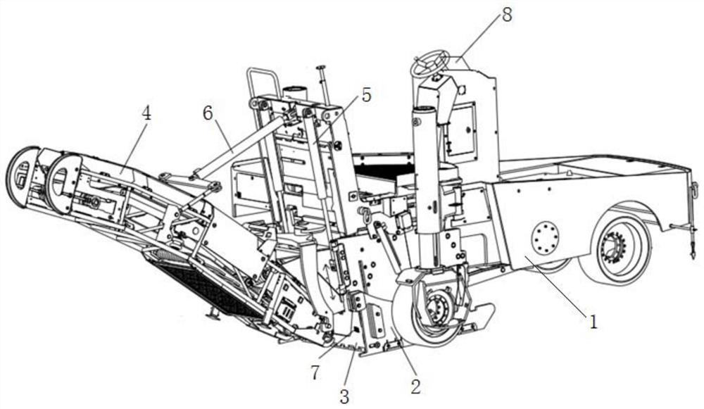
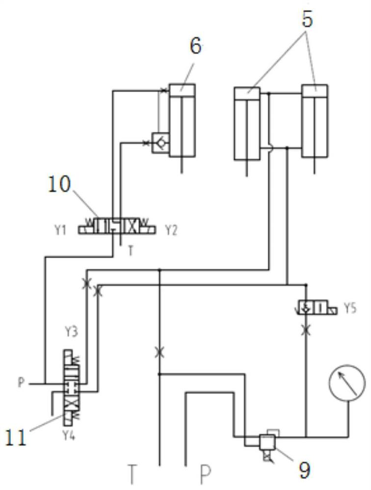
[0028] The present invention provides a control system of a milling machine, the control system is mainly used to control the scraper 3 and the feeding device 4 in the milling machine, such as figure 1 and figure 2 As shown, the scraper 3 is slidingly connected to the milling bin 2 at the rear of the fuselage 1, one end of the feeding device 4 is hinged to the scraper 3, and the other end of the feeding device 4 extends obliquely upward in a direction away from the scraper 3, The material conveying belt ...


PUM


Abstract

The invention relates to the technical field of engineering machinery, in particular to a milling machine control system and control method. The control system includes a vibration signal detector and a back pressure valve, the vibration signal detector is arranged on the scraper, and the back pressure valve is connected to the first lift cylinder; the controller can collect the vibration signal detected by the vibration signal detector, and can The received vibration signal adjusts the back pressure of the back pressure valve to realize the function of automatic pressure regulation, especially through logic control, it can realize the automatic diagnosis, preliminary elimination and alarm function of the fault in the working condition of the scraper, and form an anti-deformation protection for the scraper . The control system also includes a first displacement detector. The controller can calculate and convert the displacement A detected by the first displacement detector into the displacement B of the second lift cylinder, and control the action of the reversing valve of the second lift cylinder to make the second lift cylinder The oil cylinder drives the conveying device to lift or lower the displacement B to realize the coordinated movement of the second lift cylinder and the first lift cylinder.

Description

technical field [0001] The invention relates to the technical field of engineering machinery, in particular to a milling machine control system and control method. Background technique [0002] Milling machine is one of the main equipment for asphalt concrete pavement maintenance construction. Because of its advantages of easy control, convenient and flexible operation, good maneuverability, and the direct recycling of old milling materials, it is widely used in urban municipal roads and expressway maintenance operations. project. [0003] The scraper is the key part at the rear of the milling bin, and it plays the role of supporting the feeding device and scraping the material. During operation, the lifting cylinder of the scraper is in a floating state. If the back pressure is too large, the attachment of the scraper to the ground will If the force is small, the cleanliness of the ground after milling will be less ideal; if the back pressure is too small, the adhesion of ...

Claims


Application Information

Patent Timeline
Patent Type & Authority Patents(China)
IPC IPC(8): G05B19/04E01C23/088
CPCE01C23/088G05B19/04
Inventor 许彬徐记锋李定国胡滨王彦东
Owner SHANTUI CONSTR MASCH CO LTD
Why Eureka
Try Eureka