drain cover
A technology of drainage holes and drainage channels, which is used in drainage structures, waterway systems, water supply devices, etc., can solve the problems of effectively preventing manhole covers and deodorizing, and achieves the effect of maintaining smooth flow and accelerating flow and flow rate.
- Summary
- Abstract
- Description
- Claims
- Application Information
AI Technical Summary
Problems solved by technology
Method used
Image
Examples
Embodiment 1
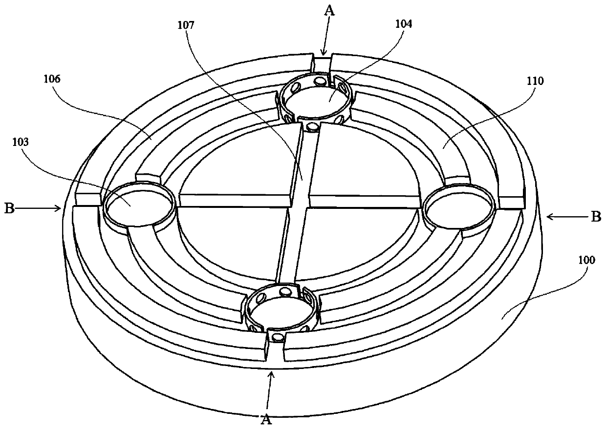
[0031] combine Figure 1-10 , the drain cover of the present embodiment, comprising:
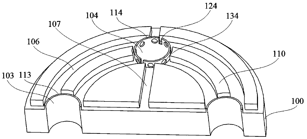
[0032] Well cover body 100 (reference figure 1 ), the outer surface of the well cover body 100 is surrounded by a well cover mounting seat 102, and the upper surface of the well cover body 100 is provided with two annular partition walls 110 with the same center; Corresponding annular grooves 106 are respectively formed between the raised circular platform and the inner partition wall 110, between the inner partition wall 110 and the outer partition wall 110, and between the outer partition wall 110 and the well cover mounting seat 102; There are two diversion grooves 107 crossing in a cross shape on the round platform, and the two ends of each diversion groove 107 respectively extend to the outer edge of the manhole cover body 100 and pass through the inner and outer partition walls 110 respectively;
[0033] Two first drainage holes 104 and two second drainage holes 103, one first draina...
Embodiment 2
[0040] refer to figure 2 , the drainage cover of this embodiment, its structure is basically the same as that of Embodiment 1, and further: the upper surface of the well cover body 100 is provided with an orifice vertical ring 114 surrounding the outer edge of the first drainage hole 104; the orifice vertical ring 114 The side wall is provided with several water holes 134 through the side wall of the vertical ring 114 of the orifice; extending downward from the first drain hole 104 is provided with an automatic water drop box 105, and the top of the automatic water drop box 105 is connected to the corresponding first drainage hole. The hole 104 is connected, and the bottom of the automatic drain tank 105 is provided with a drain hole. One side of the drain hole is connected with a water plug 125 that can seal the drain hole through a fixed rotating shaft 155. The floating ball 115 in the 105 is connected; the drain hole at the bottom of the automatic drain tank 105 communicat...
Embodiment 3
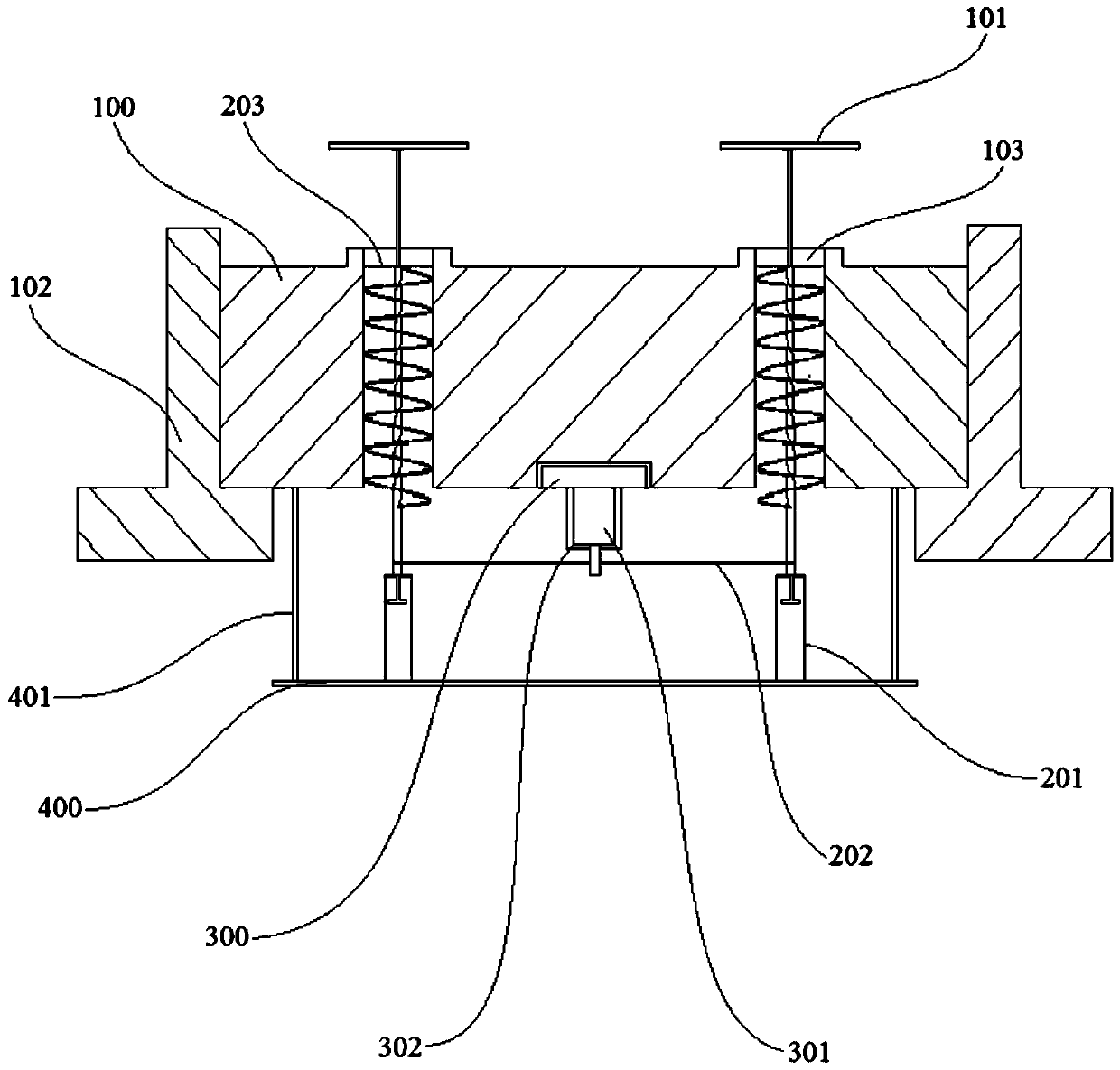
[0043] refer to Figure 8 , the structure of the drainage cover of this embodiment is basically the same as that of Embodiment 2, and further: the top of the positioning cylinder 231 is provided with a cylindrical membrane 213 that is sleeved on the outside of the buoy rod 131, and the upper end of the cylindrical membrane 213 is connected to the buoy The outer wall of the rod 131 and the lower end of the cylindrical membrane 213 are connected to the upper end of the positioning cylinder 231 .
[0044] In this embodiment, the height of the cylindrical membrane 213 is greater than the movement displacement of the floating rod 131 (that is, the distance between the position of the floating rod 131 when it is not subjected to buoyancy to the limit position where the floating rod 131 rises to under the buoyancy), The cylindrical membrane 213 can effectively prevent the water flow from entering the support seat 201 along the gap between the floating rod 131 and the positioning cyli...
PUM
 Abstract
Description
Claims
Application Information
 - R&D
- Intellectual Property
- Life Sciences
- Materials
- Tech Scout
- Unparalleled Data Quality
- Higher Quality Content
- 60% Fewer Hallucinations
Browse by: Latest US Patents, China's latest patents, Technical Efficacy Thesaurus, Application Domain, Technology Topic, Popular Technical Reports.
© 2025 PatSnap. All rights reserved.Legal|Privacy policy|Modern Slavery Act Transparency Statement|Sitemap|About US| Contact US: help@patsnap.com


