
A simple forming method of armature coil with different slots in dc traction motor

An armature coil, DC traction technology, applied in the manufacture of motor generators, electric components, electrical components, etc., can solve the problem that the upper side is difficult to accurately correspond to two adjacent slots, the lower side of the armature coil is poorly compliant, and the lower side is difficult to fit. The overall section thickness and other problems can achieve the effect of easy inlay, good integration and high degree of conformity

Inactive Publication Date: 2018-12-21
CHENGDU CRRC ELECTRIC MOTOR CO LTD
View PDF6 Cites 0 Cited by
  • Summary
  • Abstract
  • Description
  • Claims
  • Application Information

AI Technical Summary

Problems solved by technology

Since the two sets of armature coils have three corners at the nose and the lower side, and the inner and outer windings of the lower side of the combined armature coils are formed in two sets of moulds, the corners will inevitably appear incongruous, so after the combination The lower side of the armature coil is not well-fitted, resulting in a thicker overall section of the lower side, and it is also difficult for the upper side to accurately correspond to the adjacent two slots.

Method used


Image

  • A simple forming method of armature coil with different slots in dc traction motor
  • A simple forming method of armature coil with different slots in dc traction motor
  • A simple forming method of armature coil with different slots in dc traction motor

Examples


Embodiment Construction

[0018] In order to have a clearer understanding of the technical features, purposes and effects of the present invention, the specific implementation manners of the present invention will now be described with reference to the accompanying drawings.

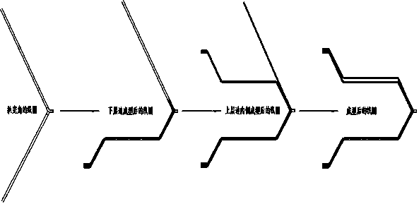
[0019] The present invention proposes a simple forming method for different-slot armature coils of DC traction motors, such as figure 1 shown, including the following steps:

[0020] S1. Armature coil pretreatment: stick two sets of armature coils together, and perform cornering treatment on the middle part of the armature coil to form a nose, and then clip the nose of the armature coil held on a knockout mould;

[0021] S2. Treatment of the lower side of the armature coil: protect the armature coil with a non-metallic pad, and use a metal hammer to strike the non-metallic pad to shape the armature coil, and connect the lower side of the armature coil with the The knocking mold is fully fitted, and then the lower edge after th...


PUM


Abstract

The invention discloses a simple molding method of armature coils with different slots of a DC traction motor, comprising the following steps: (1) two groups of armature coils are closely attached toeach other to perform angle stripping treatment and form a nose part, and then the nose part of the armature coil is clamped on a knocking mold; (2), knocking the non-metal cushion block on the plateof the armature coil by a metal hammer, so that the low layer edge is completely in contact with the knocking mold; (3) forming the inner side group coil of the upper layer side by the method of step2, wedging the middle section of the inner side group coil of the upper layer side with a stopper, and then forming the outer side group coil of the upper layer side by the method of step 2. The different slot armature coil are formed on the same set of knock mould, the double clamping in the grouping molding process is avoided, the molding efficiency is high, the adherence degree of the lower layer edge after molding is high, and the integrality is good. In addition, a stopper is skillfully used to simulate the state of the different slot armature coil when the wire is embedded, so that the different slot spacing on the upper side is accurate.

Description

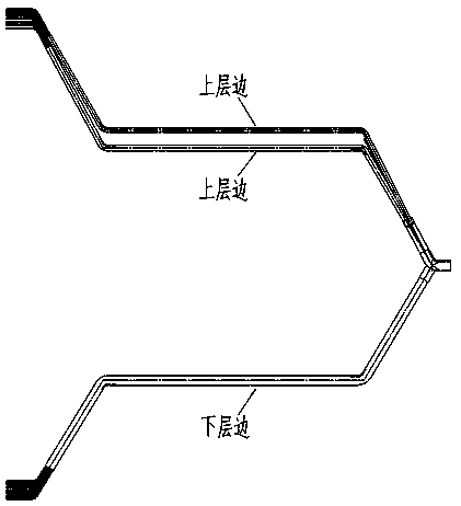
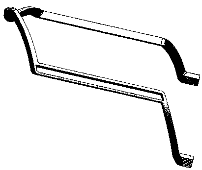
technical field [0001] The invention relates to an armature coil of a DC motor, in particular to a simple forming method for an armature coil of a DC traction motor with different slots. Background technique [0002] The traditional forming method of different-slot armature coils for DC traction motors is as follows: figure 2 and image 3 The shown armature coils are regarded as two groups, namely winding 1 and winding 2. Two sets of knocking molds are used to shape winding 1 and winding 2 respectively, and then the lower layers of winding 1 and winding 2 are combined together. Since the two sets of armature coils have three corners at the nose and the lower side, and the inner winding and outer winding of the lower side of the combined armature coil are formed in two sets of moulds, the corners will inevitably appear disobedient, so after the combination The lower side of the armature coil is less compliant, resulting in a thicker overall section of the lower side, and it...

Claims


Application Information

Patent Timeline
IPC IPC(8): H02K15/04
CPCH02K15/0435
Inventor 熊剑林炯范国安罗皓文赵琬倩魏强钱诚高亮杨锴
Owner CHENGDU CRRC ELECTRIC MOTOR CO LTD
Learn More