
M-cavity sand making machine

A technology of sand making machine and machine body, which is applied in the direction of grain processing, etc., which can solve the problems of high labor intensity, unsmooth sand discharge, and low sand making efficiency, and achieve the effects of reducing labor intensity, convenient replacement and maintenance, and ensuring production rhythm

Inactive Publication Date: 2018-12-21
SICHUAN JIANGYOU XINCHUAN MINE MACHINERY
View PDF7 Cites 2 Cited by
  • Summary
  • Abstract
  • Description
  • Claims
  • Application Information

AI Technical Summary

Problems solved by technology

The labor intensity of the operator of this equipment is high, and the efficiency of sand making is low
At present, there are also sand making machines that set a screening mechanism in the machine and control the size of the material particles by reducing the distance between the mechanism and the inner liner of the body. Unsmooth sand occurs

Method used


Image

  • M-cavity sand making machine
  • M-cavity sand making machine
  • M-cavity sand making machine

Examples


Embodiment Construction

[0036] The technical solution of the present invention will be further described in detail below in conjunction with the accompanying drawings, but the protection scope of the present invention is not limited to the following description.

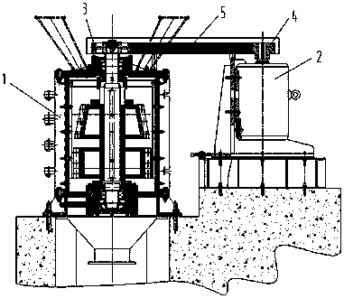
[0037] Such as figure 1 As shown, a M-cavity sand making machine includes a body 1 and a motor 2, and the body 1 includes a shell and a rotating device.

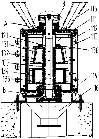
[0038] Such as figure 2 As shown, the housing includes a base 114, a hollow cylindrical cylinder 112 is fixedly arranged on the base 114, a wear-resistant liner 113 is arranged on the inner wall of the cylinder 112, a top plate 111 is fixedly arranged on the top of the cylinder 112, and the top plate 111 The top surface of the top surface is fixedly provided with the feeding port 115, the bottom of the base 114 is provided with the feeding port 116, the top plate 111 and the base 114 are all processed with openings, the feeding port 115 and the feeding port 116 pass through the opening ...


PUM


Abstract

The invention discloses an M-cavity sand making machine, and relates to the field of sand making machines. The M-cavity sand making machine comprises a machine body and a motor, the machine body comprises a shell body and a rotating device, the shell body comprises a feeding port, a top plate, a cylinder body, a base and a discharging port which are sequentially arranged from top to bottom, and awear-resistant lining plate is arranged in the cylinder body; the rotating device comprises a rotating shaft, a conical boss type upper rotating frame, a connecting spacer bush and a cylindrical lowerrotating frame are sequentially and fixedly arranged on the rotating shaft, a wear-resistant plate hammer a is arranged on the upper rotating frame, and a wear-resistant plate hammer b is arranged onthe lower rotating frame; one end of the rotating shaft is inserted into the center of the base and is movably connected with the base, the lower rotating frame is arranged close to the base, the other end of the rotating shaft penetrates through the center of the top plate and is movably connected with the top plate, a belt wheel a is fixedly arranged at the end of the rotating shaft, and a beltwheel b is fixedly arranged at the end of an output shaft of the motor; and the M-cavity sand making machine further comprises a belt, and the belt wheel a and the belt wheel b are in transmission connection through the belt. According to the M-cavity sand making machine, materials can be fully crushed in the machine, the sand making efficiency is high, moreover, discharging is smooth, manual operation and screening are not needed, and the labor intensity is reduced.

Description

technical field [0001] The invention relates to the field of sand making machines, in particular to an M-cavity sand making machine. Background technique [0002] With the rapid development of the construction industry, the demand for sand and gravel is increasing. However, natural sand and gravel are non-renewable resources in a short period of time. After years of development, natural sand and gravel are almost exhausted, and the excavation of sand and gravel has caused serious damage to resources and the environment. In order to meet people's needs for sand and gravel, industrial sand making machines have emerged as the times require. Sand making machines can crush rocks, ores and other stones into industrial sand, which can be used instead of natural sand. [0003] The sand making machine is a kind of vertical shaft crusher. The material enters the body from the feed port, and then the material is struck by the blow bar, impacted by the material and the material, impact...

Claims


Application Information

Patent Timeline
Patent Type & Authority Applications(China)
IPC IPC(8): B02C13/18B02C13/28B02C13/282B02C13/286B02C13/30B02C13/26
CPCB02C13/18B02C13/26B02C13/2804B02C13/282B02C13/286B02C13/30B02C2013/28618
Inventor 唐铭
Owner SICHUAN JIANGYOU XINCHUAN MINE MACHINERY
Learn More