Numerically controlled low-intensity focused ultrasonic excitation and imaging system

A technology for focusing ultrasound and imaging systems, which is applied in the directions of ultrasound/sonic/infrasonic Permian technology, ultrasound/sonic/infrasonic image/data processing, ultrasound/sonic/infrasonic diagnosis, etc., which can solve the positioning range and position inaccuracy and other problems, to achieve the effect of increasing positioning accuracy, increasing precision, and fast adjustment speed

Inactive Publication Date: 2021-03-16
CHONGQING MEDICAL UNIVERSITY
View PDF9 Cites 0 Cited by
  • Summary
  • Abstract
  • Description
  • Claims
  • Application Information

AI Technical Summary

Problems solved by technology

[0005] The technical problem solved by the present invention is to provide a digitally controlled low-intensity focused ultrasonic excitation and imaging system to solve the problem of inaccurate positioning range and position when the existing ultrasonic imaging system performs focus positioning

Method used


Image

  • Numerically controlled low-intensity focused ultrasonic excitation and imaging system
  • Numerically controlled low-intensity focused ultrasonic excitation and imaging system
  • Numerically controlled low-intensity focused ultrasonic excitation and imaging system

Examples


Embodiment 1

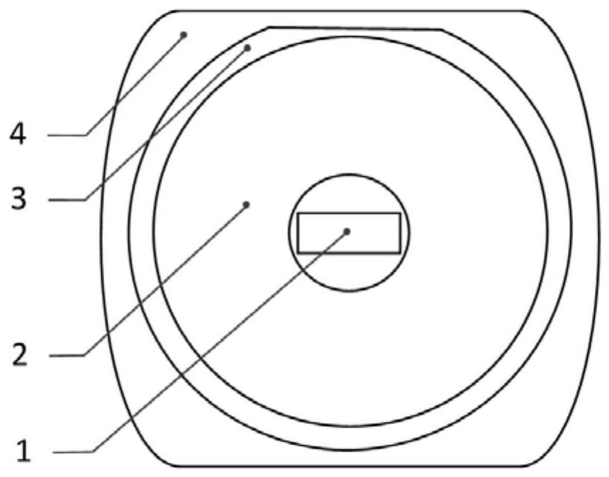
[0075] Such as figure 1 As shown: CNC low-intensity focus ultrasonic excitation and imaging system, including: detection probes and control modules;

[0076] The detection probe includes a probe guard housing 4, and a bracket 3 is mounted in the probe guard 4, a bracket shaped focus array transmitter 2 is mounted on the bracket 3. The focus array transmitter 2 is located in the center position of the focus, and the hole is placed. The imaging probe is provided, and the imaging probe is also referred to as an imaging transducer 1, and the imaging transducer 1 is used to convert the input electrical power to a frequency of 1-5 MHz ultrasonic waves, and the imaging transducer 1 is also used to receive ultrasonic information and receive according to receipt. Ultrasonic signal display microbubble targets before and the ultrasound image after the blasting. The number of arrays transmitted by the focus array transmitter 2 is 128-256.

[0077] The control module, the control module, and ...

Embodiment 2

[0130] The difference between the second embodiment and the embodiment is, if Figure 49 with 50 As shown in the second embodiment, an anti-iron heat dissipation device is also provided, and the anti-iron heat dissipation device is disposed on the side wall of the probe protective case 4, and the anti-iron heat dissipation device includes: a thermally conductive plate 6 disposed on the side wall of the probe guard 4, a probe A heat dissipation plate 5 is provided on the outer wall of the protective case 4, the heat dissipation plate 5 and the heat conductance plate 6 hinge, the heat dissipation plate 5 and the heat conductance plate 6 are arranged to bring the heat sink 5 and the probe protective case 4 torsion spring, heat dissipation Both the plate 5 and the heat conductance plate 6 use a metal material having a good thermal conductivity. A solution chamber 7 is provided between the heat sink 5 and the heat conductance plate 6, and the solution chamber 7 is slidably connected to...


PUM


Abstract

The invention relates to the technical field of ultrasonic imaging, in particular to a numerical control type low-intensity focused ultrasonic excitation and imaging system. The system comprises a detection probe, wherein the detection probe comprises an imaging transducer, and the detection probe further comprises a spherical-crown-shaped focusing multi-array emitter, the imaging transducer is arranged at the center of the focusing array emitter, and a three-dimensional focus is formed when the focusing array emitter performs focusing in vivo. The numerical control type low-intensity focusedultrasonic excitation and imaging system is based on the digital control technology, and three-dimensional focusing is performed through the spherical-crown-shaped focusing multi-array emitter, so that the focusing range is clearer, and the positioning range and the accuracy of the positioning position are increased during focusing positioning.

Description

Technical field [0001] The present invention relates to the field of ultrasonic imaging, and more particularly to a numerical low intensity focus ultrasonic excitation and imaging system. Background technique [0002] The ultrasonic molecular imaging is to construct the target molecule-specific antibody or ligand to the acoustic contrast agent surface, which actively binds to the target area to perform specific ultrasonic molecular imaging. [0003] At present, the ultrasonic molecular imaging is not only used for diagnosis of disease, but the progress of imaging technology has made the diagnosis and treatment of the disease. Therefore, domestic and foreign scholars are loaded into genes or drugs on the surface or inside of the contrast agent, making ultrasonic contrasts into a safe, convenient non-viral vector, targeted release drugs and genes, thereby achieving the purpose of treating diseases. The size of the ultrasonic microvescoal film is comparable to the red blood cells, w...

Claims


Application Information

Patent Timeline
Patent Type & Authority Patents(China)
IPC IPC(8): A61B8/08A61M37/00
CPCA61B8/085A61B8/4444A61M37/0092
Inventor 曹阳刘竞飞冉海涛王志刚李攀
Owner CHONGQING MEDICAL UNIVERSITY
Why Eureka
Try Eureka