ONU anomaly detection method, device, OLT, and optical network

An anomaly detection, optical network unit technology, applied in the optical network field, can solve the problems of high complexity, small ONU range, and large business impact, and achieve the effect of simple implementation, strong real-time performance, and comprehensive guarantee.

Active Publication Date: 2018-12-18
CHINA TELECOM CORP LTD
View PDF3 Cites 9 Cited by
  • Summary
  • Abstract
  • Description
  • Claims
  • Application Information

AI Technical Summary

Problems solved by technology

Among them, the long light emission affects all end users under the PON port, so it is relatively easy to identify, while the ONU with light emission drift is often difficult to accurately identify and detect because of its random and small range of influence, and the fault phenomenon is easily confused with other types of faults.
At present, the commonly used abnormal light detection scheme is to use idle time slot optical power detection for the PON port on the OLT side, which can only detect the presence of a full-length light-emitting ONU. It is necessary to combine the ONU optical module / power off method to locate the faulty ONU, and it is impossible to accurately locate the light-emitting ONU. Faulty ONU with Gap Drift
At the same time, the uplink DBA authorization period is us-ms level. If dozens of ONU time slots under the PON port are detected at the same time, the complexity is high, OLT resource overhead is large, and real-time performance is difficult to guarantee; if only a single time slot is detected, the omission rate is high.
Therefore, the existing abnormal lighting detection scheme only targets ONU long-lighting faults (the long lighting cycle exceeds 1 DBA authorization cycle), and the location of the fault requires turning off the optical module power of all ONUs under the PON port, which has a great impact on the business, while the lighting drift only Affects the condition of adjacent ONUs, and there are difficulties in the detection and positioning of abnormal luminescence drift

Method used


Image

  • ONU anomaly detection method, device, OLT, and optical network
  • ONU anomaly detection method, device, OLT, and optical network
  • ONU anomaly detection method, device, OLT, and optical network

Examples


Embodiment Construction

[0029] The present invention will be described more fully hereinafter with reference to the accompanying drawings, in which exemplary embodiments of the invention are illustrated. The following will clearly and completely describe the technical solutions in the embodiments of the present invention with reference to the accompanying drawings in the embodiments of the present invention. Obviously, the described embodiments are only some, not all, embodiments of the present invention. Based on the embodiments of the present invention, all other embodiments obtained by persons of ordinary skill in the art without making creative efforts belong to the protection scope of the present invention. The technical solution of the present invention will be described in various aspects below in conjunction with various figures and embodiments.

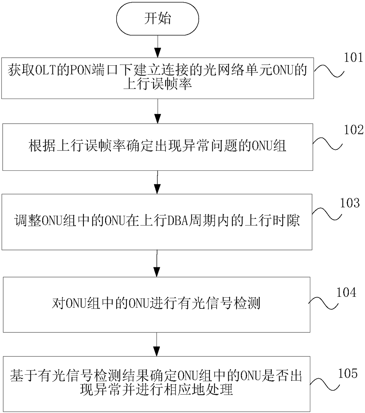
[0030] figure 1 It is a flowchart of an embodiment of the ONU abnormality detection method according to the present invention, such as figure 1 S...


PUM


Abstract

The invention discloses an ONU anomaly detection method, a device, an OLT and an optical network. The method comprises the following steps: obtaining an uplink frame error rate of an ONU which is connected under a PON port of the OLT; determining an abnormal problem ONU group according to the uplink frame error rate; adjusting the uplink time slot of ONU in the abnormal problem ONU group in the uplink DBA cycle; performing optical signal detection for ONUs in the ONU group with abnormal problems. Based on the detection result of the optical signal, it is determined whether the ONU in the ONU group with the abnormality problem has an abnormality or not, and the abnormality is processed accordingly. The invention realizes the detection and positioning of the luminous drift ONU without affecting the normal user service, can be aimed at the detection on demand, does not need to do the traversal test on all ONUs, does not affect the upstream transmission bandwidth efficiency of the originalPON port in the detection process of the ONU under test, locates the fault ONU more quickly and accurately, and does not need to interrupt the normal service.

Description

technical field [0001] The invention relates to the technical field of optical networks, in particular to an ONU anomaly detection method, device, OLT and optical network. Background technique [0002] At present, the passive optical network PON (Passive Optical Network, Passive Optical Network) system applied on a large scale in the existing network mostly adopts a 1:N structure, and the uplink transmission generally adopts the TDMA (Time Division Multiple Access, Time Division Multiple Access) method. The ONU (Optical Network Unit, optical network unit) terminal uploads data sequentially and time-sharing in the uplink DBA (Dynamic Bandwidth Allocation, dynamic bandwidth allocation) authorized time slot issued by the OLT (Optical Line Terminal, optical line terminal). Some ONUs in the current network have abnormal light emission or light emission drift due to optical module aging or software reasons, which occupy the upload time slots of other adjacent ONUs under the PON po...

Claims


Application Information

Patent Timeline
Patent Type & Authority Applications(China)
IPC IPC(8): H04B10/079
CPCH04B10/0791H04B10/0795
Inventor 李浩琳蒋铭杜喆张德智
Owner CHINA TELECOM CORP LTD
Why Eureka
Try Eureka