A street scene image difference comparison method and a device
An image and street view technology, applied in the field of computer vision, to achieve the effect of reducing labor intensity, efficient automatic detection method, and making up for time-consuming and labor-intensive
- Summary
- Abstract
- Description
- Claims
- Application Information
AI Technical Summary
Problems solved by technology
Method used
Image


Examples
Embodiment 1
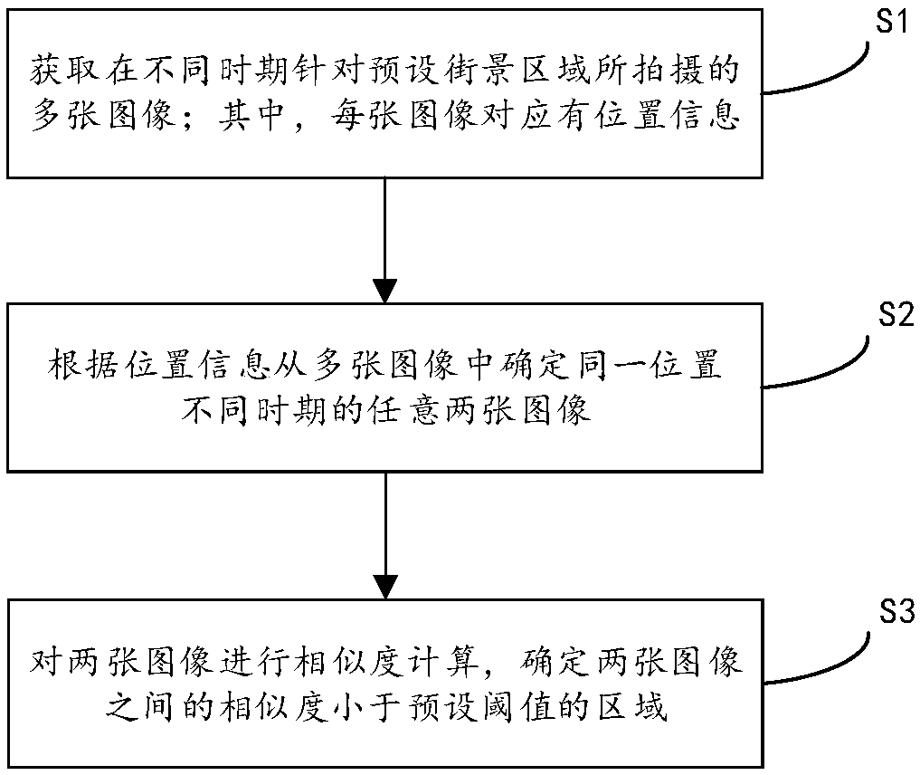
[0039] figure 1 is a flowchart of a street view image difference comparison method according to an embodiment of the present invention, such as figure 1 As shown, the method includes the following steps:
[0040] Step S1: Obtain multiple images taken in different periods for the preset street view area; wherein, each image corresponds to location information; the location information can be at least information such as street name, street number, latitude and longitude;
[0041] Step S2: Determine any two images of the same location in different periods from multiple images according to the location information;
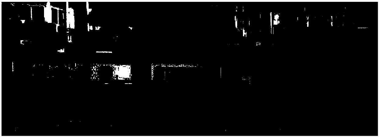
[0042] Step S3: Carry out similarity calculation on the two images, and determine an area where the similarity between the two images is smaller than a preset threshold.
[0043] This embodiment provides an efficient automatic detection method for finding differences in street view images taken in different periods, which not only reduces the labor intensity of pro...
Embodiment 2
[0065] Figure 12 It is a comparison flow chart of changing positions of street view images according to an embodiment of the present invention, such as Figure 12 As shown, the process includes the following steps:
[0066] S1: Obtain the image data I of the same street view area in two periods T1 / T2 from the street view image database, and the position information P corresponding to each image, (T1={I1,P1}). This step is specifically realized by the following method: the professional street view image collection vehicle simultaneously acquires, and each image corresponds to location information, latitude and longitude, etc.
[0067] S2: According to the location information of the street view image, find two street view images of the same location in different periods.
[0068] This step is specifically implemented by the following method: select a street view image I1 in T1, and obtain its location information P1. Search the position P2 closest to P1 in T2, and then obta...
Embodiment 3
[0080] corresponds to figure 1 The street view image difference comparison method introduced, this embodiment provides a street view image difference comparison device, such as Figure 13 Shown is a structural block diagram of a street view image difference comparison device, which may include: an image acquisition module 10 , an image processing module 20 , and a difference comparison module 30 . Those skilled in the art can understand that, Figure 13 The structure of the street view image difference comparison device shown in does not constitute a limitation to the street view image difference comparison device. The street view image difference comparison device may include more or less components than those shown in the illustration, or combine some components, or different components. layout.
[0081] Combine below Figure 13 A specific introduction to each component of the street view image difference comparison device:
[0082] The image acquisition module 10 is use...
PUM
 Abstract
Description
Claims
Application Information
 - R&D
- Intellectual Property
- Life Sciences
- Materials
- Tech Scout
- Unparalleled Data Quality
- Higher Quality Content
- 60% Fewer Hallucinations
Browse by: Latest US Patents, China's latest patents, Technical Efficacy Thesaurus, Application Domain, Technology Topic, Popular Technical Reports.
© 2025 PatSnap. All rights reserved.Legal|Privacy policy|Modern Slavery Act Transparency Statement|Sitemap|About US| Contact US: help@patsnap.com