
Novel pneumatic membrane valve

A pneumatic membrane valve, a new type of technology, applied in the direction of lift valve, valve details, valve device, etc., can solve the problems of poor valve sealing, valve core erosion, etc., to achieve extended service life, good flow control performance, and reduce fluid erosion erosion the effect of the possibility of

Active Publication Date: 2018-12-18
普雷沃流体控制科技(芜湖)有限公司
View PDF6 Cites 3 Cited by
  • Summary
  • Abstract
  • Description
  • Claims
  • Application Information

AI Technical Summary

Problems solved by technology

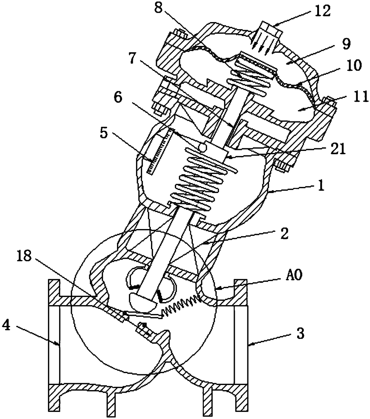
However, in practical applications, when the fluid flows through the valve, the fluid directly washes against the valve core, causing erosion to the sealing surface of the valve core, which may easily cause the valve to be not tightly sealed after it is closed.

Method used


Image

  • Novel pneumatic membrane valve
  • Novel pneumatic membrane valve

Examples


Embodiment Construction

[0018] The following will clearly and completely describe the technical solutions in the embodiments of the present invention with reference to the accompanying drawings in the embodiments of the present invention. Obviously, the described embodiments are only some, not all, embodiments of the present invention. Based on the embodiments of the present invention, all other embodiments obtained by persons of ordinary skill in the art without making creative efforts belong to the protection scope of the present invention.

[0019] In the description of the present invention, it should be noted that the terms "upper", "lower", "inner", "outer", "end", "front end", "rear end", "both ends", "one end" , "the other end" and other indicated orientations or positional relationships are based on the orientations or positional relationships shown in the drawings, which are only for the convenience of describing the present invention and simplifying the description, rather than indicating o...


PUM


Abstract

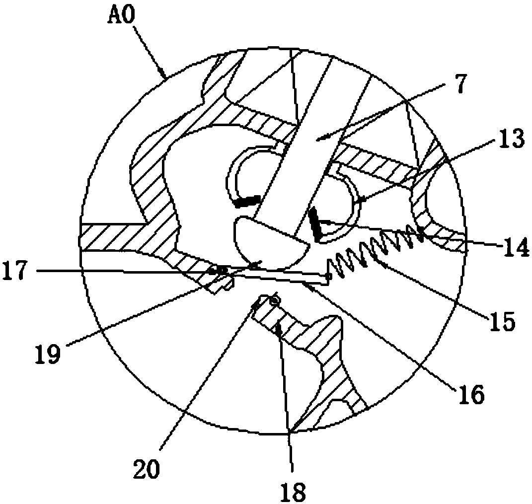
The invention discloses a novel pneumatic membrane valve. The novel pneumatic membrane valve comprises a valve body, a water inlet, a water outlet and a valve base, wherein the water inlet and the water outlet are formed in the two sides of the valve body correspondingly. An air chamber is arranged at the upper end of the valve body. The air chamber is sequentially divided by a membrane into a membrane chamber upper cavity and a membrane chamber lower cavity from top to bottom. A valve rod is arranged in the valve body in a penetration manner. A spring is arranged at the upper end of the valverod. The spring is arranged in the membrane chamber lower cavity and abuts against the lower surface of the membrane. A valve element is connected to the bottom of the valve rod. A valve element protection cover is arranged at the upper portion of the valve element and fixedly connected with the inner side wall of the valve body. The upper surface of the valve base is connected with a valve platethrough a rotation shaft. The valve element is arranged over the valve plate. A reset spring is connected to the other end of the valve plate, and the other end of the reset spring is fixed to the inner side wall of the valve body. The novel pneumatic membrane valve is provided with the valve element protection sleeve, fluid is prevented from directly scouring the valve element, the possibility that the valve element is scoured and eroded by fluid is reduced, and the service life of the valve is prolonged.

Description

technical field [0001] The invention relates to the technical field of valve equipment, in particular to a novel pneumatic membrane valve. Background technique [0002] The key technology of the membrane valve lies in the membrane valve core, the adjustment control and stability of the precision of the membrane valve core directly affect the performance of the pressure reducing valve. For example, the Chinese Patent Publication No. CN107448665A discloses a pneumatic membrane valve, which includes a membrane chamber, a valve body, a membrane, a fixed core, a spring, a valve seat, a push rod, a valve stem, a spool, a balance valve and a vent valve. The thin film can be easily moved and a large stroke can be performed through the thin film, the flow control performance is good, the stability and stability and the pressure adjustment precision are high, the sensitivity is high, the assembly process is simple, and the use is convenient. However, in practical applications, when t...

Claims


Application Information

Patent Timeline
IPC IPC(8): F16K31/126F16K1/36F16K1/32
CPCF16K1/32F16K1/36F16K31/126
Inventor 胡旭东林富赟吴志华
Owner 普雷沃流体控制科技(芜湖)有限公司
Learn More