


Quick Research
Generate reliable direction feasibility study reports for your R&D in just a few steps.

Technical Q&A
Discover and master advanced knowledge NOW. Basics, ideas, possibilities, all at once.

Find Solutions
As an expert in R&D theories, this can generate solutions to your technical problems instantly.

Evaluate Feasibility
Analyze your overall solution with one click, know your potential R&D risks in advance.

Monitor Landscape
Get weekly tech updates, stay abreast of the latest tech innovations and key insights.
Method and steel box girder for supplementing internal weld at joint of U-rib of steel box girder and panel
A steel box girder and joint technology, applied in bridges, bridge maintenance, bridge reinforcement, etc., can solve problems such as fatigue cracks, affecting bridge life and driving safety, fatigue cracking, etc., to extend service life, reduce maintenance costs, reduce Effects of direct and indirect losses
- Summary
- Abstract
- Description
- Claims
- Application Information
AI Technical Summary
Problems solved by technology
Method used
Image

Examples
Embodiment 1
[0041] Such as Figure 1-Figure 4 As shown, a method for supplementing the inner weld at the connection between the U-rib of the steel box girder and the panel of this embodiment includes the following steps:
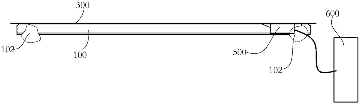
[0042] S1, Open a copy hole on the steel box girder of the built steel bridge to facilitate the welding system to enter the U rib;
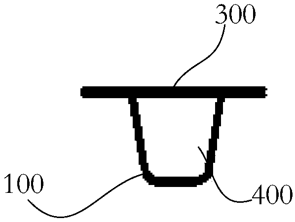
[0043] S2, placing the welding system of the inner weld supplementary equipment in the space 400 formed by the inner U-rib 100 and the panel 300 of the steel box girder from the profiling hole 102;
[0044] S3, the welding system walks along the length direction of the U-rib 100, and simultaneously welds the U-rib 100 and the panel 300 from the inside of the U-rib 100;
[0045] S4, after the welding is completed, the position of the profiling hole 102 is filled, and after filling, the filling position of the profiling hole is treated with anti-rust coating.
[0046] Among them, for different steel box girder structures, there are two imp...
Embodiment approach 1
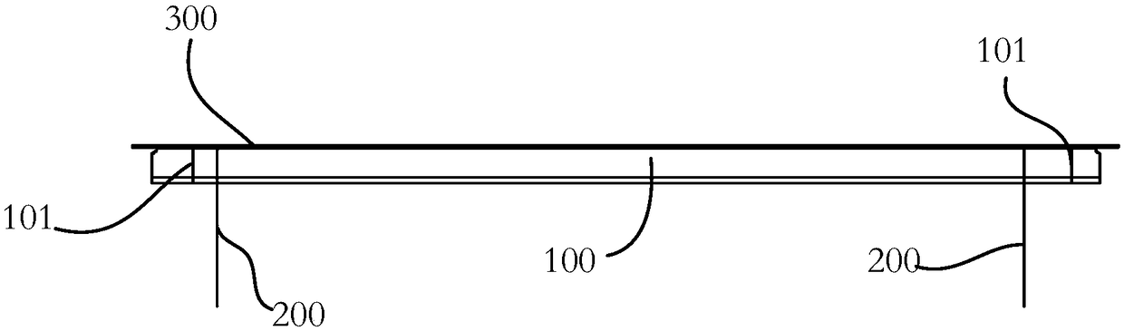
[0047] Embodiment 1: S1 is specifically, for example, Figure 1-Figure 4 As shown, a profiling hole 102 is provided at one end of the U rib 100 in the steel box girder or profiling holes 102 are respectively provided at both ends of the U rib 100 or profiling holes 102 are provided on the panel 300 . The profiling hole can be of any shape and size to facilitate the welding system to enter the U-rib. The position of the copy hole can be flexibly selected. In order to minimize the damage to the U rib, the copy hole can be set as close to the end as possible, so that the welding system can enter the space formed between the U rib and the panel. It is convenient to fill after welding, and it does not affect other U ribs to supplement the inner weld. The position of the profiling hole can be set on the top of the U-rib or the side of the U-rib.
Embodiment approach 2
[0048] Implementation mode two: if Figure 1-Figure 4 As shown, when there is an end sealing plate 101 in the U rib 100, the profiled hole 102 is opened at the position of the U rib 100 close to the end sealing plate 101, and the end sealing plate 101 Cutting: when the U-rib 100 has no end sealing plate 101 , open the profiling hole 102 at any position of the U-rib 100 . Setting the profiling hole close to the end sealing plate can facilitate the cutting of the end sealing plate from the profiling hole, so that the welding system can walk into the space between the U rib and the panel.
[0049] The welding system of this embodiment adopts the automatic overhead welding process of gas shielded welding. The automatic overhead welding process can ensure that the welding system moves upwards and weld between the U-rib and the panel upwards; using gas shielded welding, compared with other welding methods, the visibility of the arc and molten pool is better, and the welding process c...
PUM
 Abstract
Description
Claims
Application Information
 - R&D Engineer
- R&D Manager
- IP Professional
- Industry Leading Data Capabilities
- Powerful AI technology
- Patent DNA Extraction
Browse by: Latest US Patents, China's latest patents, Technical Efficacy Thesaurus, Application Domain, Technology Topic, Popular Technical Reports.
© 2024 PatSnap. All rights reserved.Legal|Privacy policy|Modern Slavery Act Transparency Statement|Sitemap|About US| Contact US: help@patsnap.com