Hoisting tool for single blade of wind turbine generator system and hoisting method
A wind turbine, single-blade technology, applied in the direction of transportation and packaging, load suspension components, etc., can solve the problems of high cost, poor versatility, complex structure, etc., and achieve the effect of convenient operation, simple structure, and convenient attitude adjustment operation
- Summary
- Abstract
- Description
- Claims
- Application Information
AI Technical Summary
Problems solved by technology
Method used
Image
Examples
Embodiment 1
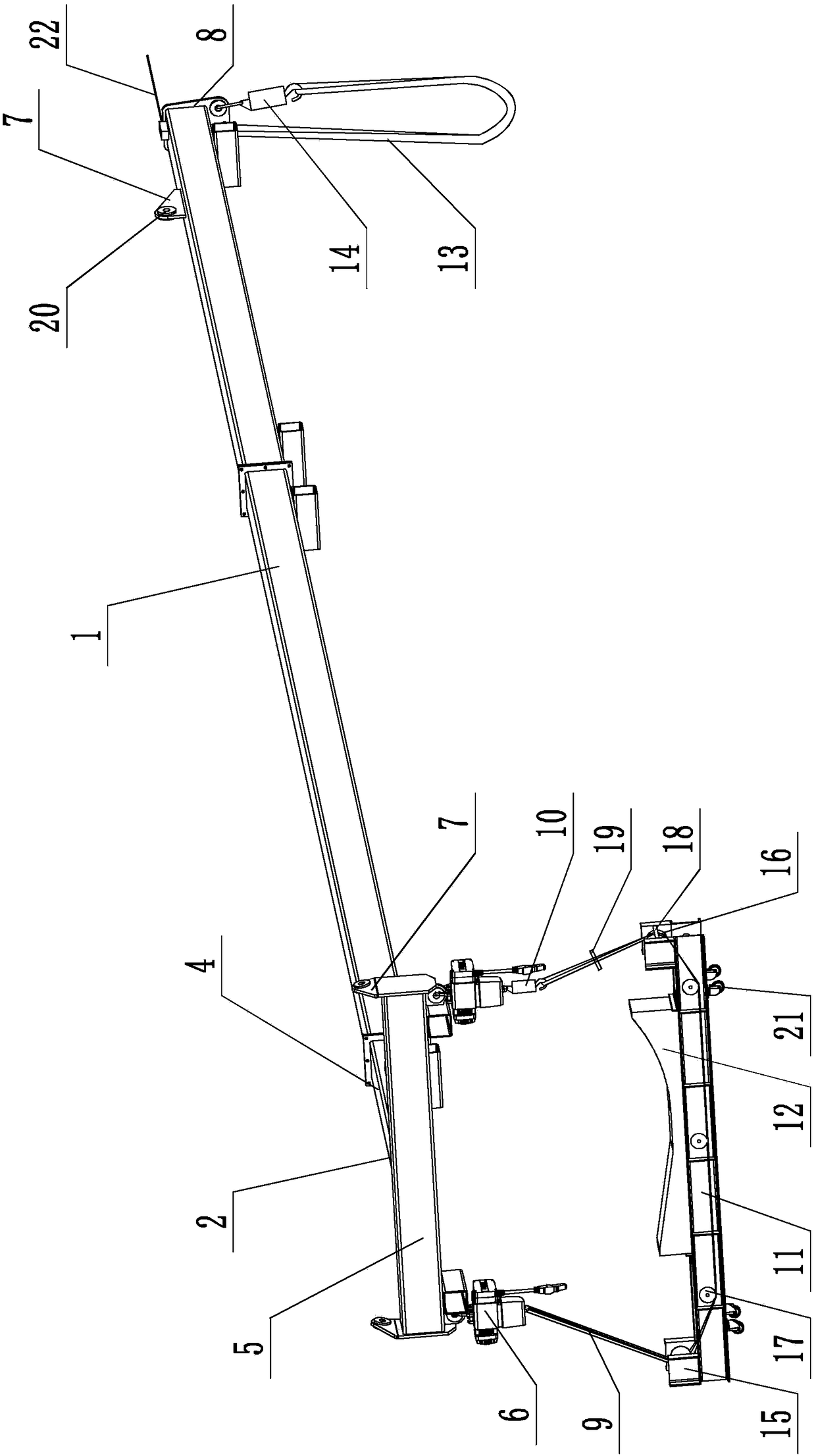
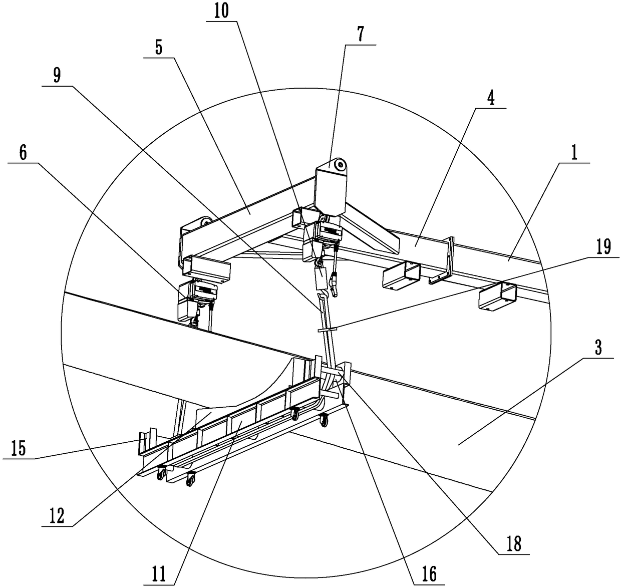
[0024] Embodiment 1: A single-blade hoisting tool for a wind power generating set (see attached figure 1 to attach image 3 ), including the main suspension beam 1 and the end suspension beam 2, the main suspension beam is long, the end suspension beam is T-shaped, the end suspension beam includes the connection beam 4 and the support beam 5, the connection beam is fastened to the main suspension beam, and the connection beam The fastening connection with the main suspension beam is realized through the connection flange. The main suspension beam includes several beam bodies fastened together, and the adjacent beam bodies are connected by connecting flanges. Both ends of the support beam are connected with the electric hoist 6 and the hoisting seat 7, and the main hoisting beam is connected with the hoisting seat and the hoisting seat 8 far away from the end of the connecting beam. , the hook of one electric hoist is connected with one end of the front sling, the front autom...
Embodiment 2
[0026] Embodiment 2: A single-blade hoisting tool for a wind power generating set (see attached Figure 4 ), its structure is similar to that of Embodiment 1, the main difference is that in this embodiment, the connecting beam and the supporting beam are connected to the supporting bottom beam 24, the supporting bottom beam is fastened to the end of the connecting beam, and the supporting beam is supported on the supporting bottom beam On, the rotating pin 25 is connected between the supporting beam and the supporting bottom beam, and the supporting beam can rotate around the rotating pin. The rotating pin has a T-shaped structure, and connecting holes are provided on the supporting beam and the supporting bottom beam. The rotating pin runs through the two connecting holes. The lower end of the rotating pin is connected with a limit nut, and the lower end of the rotating pin is connected with a limit pin to prevent The stop nut slides off the turning pin. Other structures are...
PUM
 Abstract
Description
Claims
Application Information
 - R&D
- Intellectual Property
- Life Sciences
- Materials
- Tech Scout
- Unparalleled Data Quality
- Higher Quality Content
- 60% Fewer Hallucinations
Browse by: Latest US Patents, China's latest patents, Technical Efficacy Thesaurus, Application Domain, Technology Topic, Popular Technical Reports.
© 2025 PatSnap. All rights reserved.Legal|Privacy policy|Modern Slavery Act Transparency Statement|Sitemap|About US| Contact US: help@patsnap.com


