Engine electronic control redundant system

A redundant system and engine technology, applied in the direction of engine control, electrical control, combustion engine, etc., can solve problems such as inability to diagnose, potential safety hazards, and potential safety hazards in the engine, so as to improve work stability, prevent major failures, and ensure stability. running effect

Pending Publication Date: 2018-12-14
GUANGXI YUCHAI MASCH CO LTD
View PDF7 Cites 12 Cited by
  • Summary
  • Abstract
  • Description
  • Claims
  • Application Information

AI Technical Summary

Problems solved by technology

[0002] At present, V-type internal combustion engines generally use an electronically controlled fuel system, which only monitors the cylinders on one side of the V-type internal combustion engine, and cannot monitor the working parameters of the cylinders on the other side.
This control method has the following problems: 1. The electronically controlled fuel system only monitors the engine parameters on one side, and adjusts itself according to the parameters on one side, such as alarm, correction, torque limit or shutdown. Abnormalities cannot be diagnosed, and such problems will cause potential safety hazards when users use the engine; 2. When the ECU fails, it will be stopped immediately in an emergency, and the fault state cannot be restarted. Such problems have potential safety hazards and are prone to major failures

Method used


Image

  • Engine electronic control redundant system
  • Engine electronic control redundant system
  • Engine electronic control redundant system

Examples


Embodiment Construction

[0018] The present invention will be further described below in conjunction with the specific embodiments in the drawings.

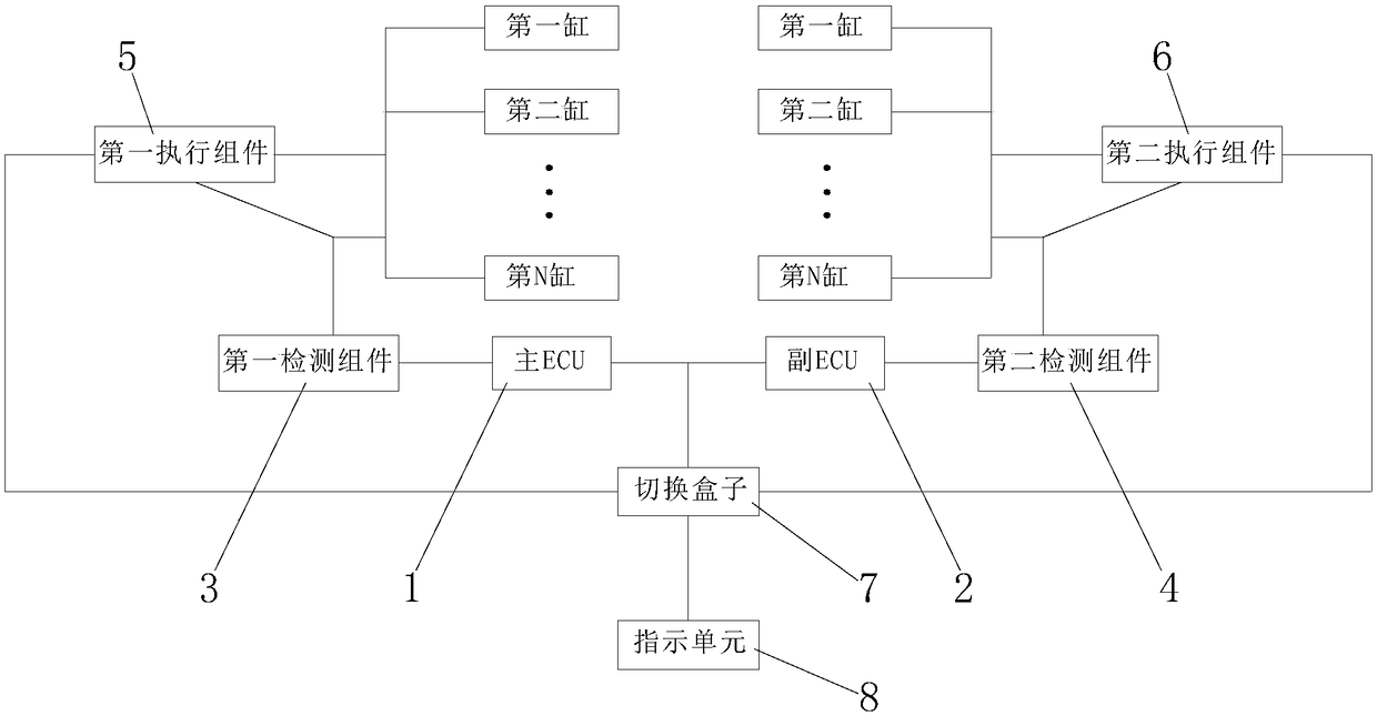
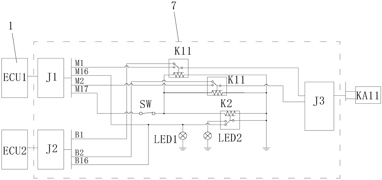
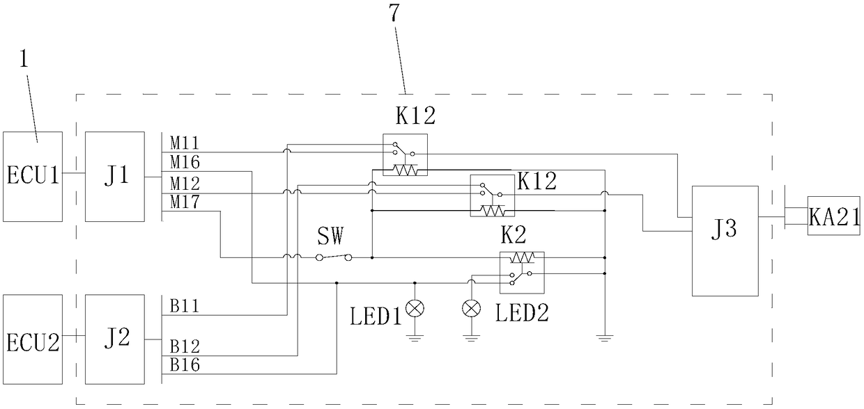
[0019] Refer to Figure 1-3 , An engine electronic control redundant system, including a main ECU1, a secondary ECU2, a first detection component 3 and a second detection component 4 for monitoring the parameters on both sides of the V-type internal combustion engine, respectively, for controlling the two sides of the V-type internal combustion engine Working first executive component 5 and second executive component 6, switching box 7 for switching control signals of main ECU1 and sub-ECU2; first detection component 3 signal output terminal is connected with main ECU1 signal input terminal, second detection component 4 The signal output terminal is connected to the signal input terminal of the secondary ECU2. The control signal output terminal of the main ECU1 is connected to the control terminals of the first executive assembly 5 and the second executive ...


PUM


Abstract

The invention discloses an engine electronic control redundant system. The engine electronic control redundant system comprises a main ECU, an auxiliary ECU, a first detecting assembly, a second detecting assembly, a first executing assembly, a second executing assembly and a switching box, wherein the first detecting assembly and the second detecting assembly are used for monitoring parameters oftwo sides of a V-type internal combustion engine correspondingly, the first executing assembly and the second executing assembly are used for controlling work of the two sides of the V-type internalcombustion engine, and the switching box is used for switching control signals of the main ECU and the auxiliary ECU. The signal output end of the first detecting assembly is connected with the signalinput end of the main ECU, the signal output end of the second detecting assembly is connected with the signal input end of the auxiliary ECU, the control signal output end of the main ECU is connected with the control end of the first executing assembly and the control end of the second executing assembly through the switching box, the control signal output end of the auxiliary ECU is connectedwith the control end of the first executing assembly and the control end of the second executing assembly through the switching box, and the communication end of the main ECU is connected with the communication end of the auxiliary ECU. According to the engine electronic control redundant system, engine parameters of the two sides of the V-type internal combustion engine can be monitored, measuresare taken according to parameter abnormity occurring on the two sides, and stable operation of the engine is guaranteed.

Description

Technical field [0001] The invention relates to the technical field of engine control, and more specifically, it relates to an engine electronic control control redundancy system. Background technique [0002] At present, V-type internal combustion engines generally use a set of electronically controlled fuel systems. The electronically controlled fuel system only monitors the cylinders on one side of the V-type internal combustion engine, and cannot monitor the operating parameters of the cylinders on the other side. This control method has the following problems: 1. The electronically controlled fuel system only monitors the engine parameters on one side, and adjusts itself according to the parameters of one side, such as alarm, correction, torque limit or shutdown, etc., and the monitoring side is normal and the other side is normal. Abnormalities cannot be diagnosed. This type of problem will cause the user to have a safety hazard when using the engine; 2. When the ECU fails,...

Claims


Application Information

Patent Timeline
IPC IPC(8): F02D41/22
CPCF02D41/22Y02T10/40
Inventor 吴彦磊温芹张万枝
Owner GUANGXI YUCHAI MASCH CO LTD
Why Eureka
Try Eureka