
Special bridge crane for brick-making equipment

A special bridge and crane technology, applied in the direction of cranes, trolley cranes, traveling mechanisms, etc., can solve the problems of inconvenient replacement, large mass inertia of moving components, high manufacturing difficulty and high cost, and achieve enhanced emission uniformity and stability, Improve the safety of on-site operations, and the effect of being less prone to falling and tilting

Pending Publication Date: 2018-12-11
SHANDONG DELUKE CRANE
View PDF5 Cites 1 Cited by
  • Summary
  • Abstract
  • Description
  • Claims
  • Application Information

AI Technical Summary

Problems solved by technology

At present, bricks are usually transported manually. Due to the harsh environment and high labor intensity, there is a strong demand for mechanized handling equipment.
Some existing equipment for mechanized brick handling mainly have the following deficiencies: (1) Because most of the existing equipment adopts a driving scheme with a vertical telescopic arm or a double-joint multi-degree-of-freedom mechanical arm scheme, the structure is complex and the movement The mass inertia of the components is large, the energy efficiency ratio is low, the manufacturing difficulty and cost are high, and they are easy to wear and fail, which greatly affects their popularization and application; (2) The pallets of the existing brick transfer equipment are fixed or movable. It is inconvenient to replace the fixed pallets when they are damaged after long-term use. The gravity of the bricks stacked on the movable pallets is stable during the brick transportation process. When the bottom of the bricks is not neatly arranged, it is easy to move. In the process of transportation, skewing and falling bricks will occur, which will cause on-site accidents in severe cases

Method used


Image

  • Special bridge crane for brick-making equipment
  • Special bridge crane for brick-making equipment
  • Special bridge crane for brick-making equipment

Examples


Embodiment Construction

[0022] To make the objectives, technical solutions, and advantages of the embodiments of the present invention clearer, the technical solutions in the embodiments of the present invention will be described clearly and completely in conjunction with the accompanying drawings in the embodiments of the present invention.

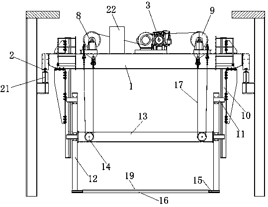
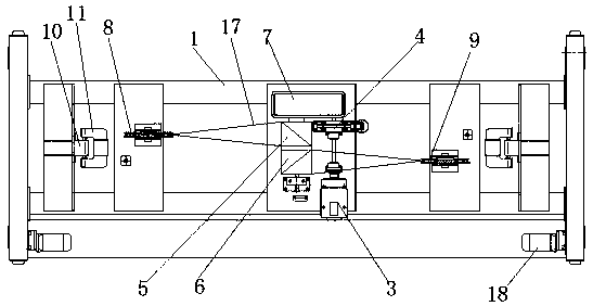
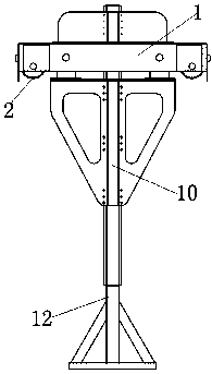
[0023] Such as Figure 1-4 In the illustrated embodiment, a bridge crane dedicated to brick making equipment includes a top base 1 and traveling wheels 2 symmetrically arranged on the left and right sides of the top base 1. The traveling wheels 2 provided on both sides of the top base 1 respectively pass through a drive motor 18 drive; the upper surface of the top seat 1 is equipped with a lifting motor 3, a lifting brake 4, a first lifting drum 5, a second lifting drum 6 and a lifting reducer 7, and the upper surface of the top seat 1 lifting motor 8 and a second top pulley 9 are symmetrically installed on the left and right sides of 3, the top seat 1 is symmetri...


PUM


Abstract

The invention relates to the technical field of brick material transportation equipment and in particular relates to a special bridge crane for brick-making equipment. According to the special bridgecrane for the brick-making equipment, a first top pulley and a second top pulley are symmetrically mounted at two sides of a hoisting motor; guide rail beams are symmetrically fixed at two sides of atop seat; the right side of the guide rail beam located at the left side is connected with an L-shaped bracket through a guide wheel pulley; the left side of the guide rail beam located at the right side is connected with an L-shaped bracket through a guide wheel pulley; a transverse beam is fixed at the upper middle part between vertical supporting plates of the two L-shaped brackets; hoisting pulleys are symmetrically mounted at the left and right sides of the transverse beam; bearing plates containing opening grooves are formed in transverse supporting plates of the bottom of the two L-shaped brackets; a brick body bearing plate is mounted between the two bearing plates containing opening grooves. According to the special bridge crane for the brick-making equipment, the structure is simplified, and the structure stability and safety are enhanced; the stability is extremely improved in loading and unloading, and transportation processes of brick materials, and the working efficiencyof transporting the brick materials is improved.

Description

Technical field [0001] The invention relates to the technical field of brick material transfer equipment, in particular to a bridge crane dedicated to brick making equipment. Background technique [0002] In brick production workshops or other construction sites where bricks are used in large quantities, there is a process link of volleying bricks. At present, bricks are usually handled by manual handling operations. Due to the harsh on-site environment and high labor intensity, there is a strong demand for mechanized handling equipment. Some existing equipment for mechanized handling of bricks mainly has the following shortcomings: (1) Because most of the existing equipment uses a traveling scheme with a vertical telescopic arm or a dual-joint multi-degree-of-freedom mechanical arm scheme, the structure is complicated and the movement is The components have large mass inertia, low energy efficiency ratio, high manufacturing difficulty and cost, easy wear and failure, which grea...

Claims


Application Information

Patent Timeline
Patent Type & Authority Applications(China)
IPC IPC(8): B66C19/00B66C9/14B66C13/08
CPCB66C9/14B66C13/08B66C19/00
Inventor 张植会毛仁德
Owner SHANDONG DELUKE CRANE
Learn More