Conveying robot for wire drawing of waste tires

A technology of waste tires and robots, which is applied in the direction of conveyors, conveyor objects, transportation and packaging, etc., can solve the problems that the spinning of waste tires cannot realize assembly line operations, waste tires cannot be fixed, and cannot continue to be extracted, etc., to ensure Accuracy, firm fixation, and the effect of reducing labor intensity

Active Publication Date: 2018-12-11
安徽新博普曼智能科技股份有限公司
View PDF11 Cites 2 Cited by
  • Summary
  • Abstract
  • Description
  • Claims
  • Application Information

AI Technical Summary

Problems solved by technology

[0004] In order to solve the above problems, the present invention provides a waste tire spinning transmission robot, which can solve the problem of unreliable fixation of waste tires before spinning, failure of assembly line operation for spinning waste tires, and after spinning waste tires on one side. Can not continue to extract the other side of the steel wire, waste tires cannot be fixed during the transmission process and other problems; can realize integrated waste tire transmission, waste tire rotation double-sided drawing, various specifications of waste tire transmission and fixing functions, with waste tire drawing The front fixing is firm, the wire drawing of waste tires can realize assembly line operation, the steel wire on the other side can be continuously extracted after the wire drawing of one side of waste tires is completed, and the waste tires can be fixed during the transmission process, etc.;

Method used


Image

  • Conveying robot for wire drawing of waste tires
  • Conveying robot for wire drawing of waste tires
  • Conveying robot for wire drawing of waste tires

Examples


Embodiment Construction

[0030] In order to make it easy to understand the technical means, creative features, objectives and effects achieved by the present invention, the present invention will be further explained below in conjunction with specific drawings. It should be noted that the embodiments in this application and the features in the embodiments can be combined with each other if there is no conflict.

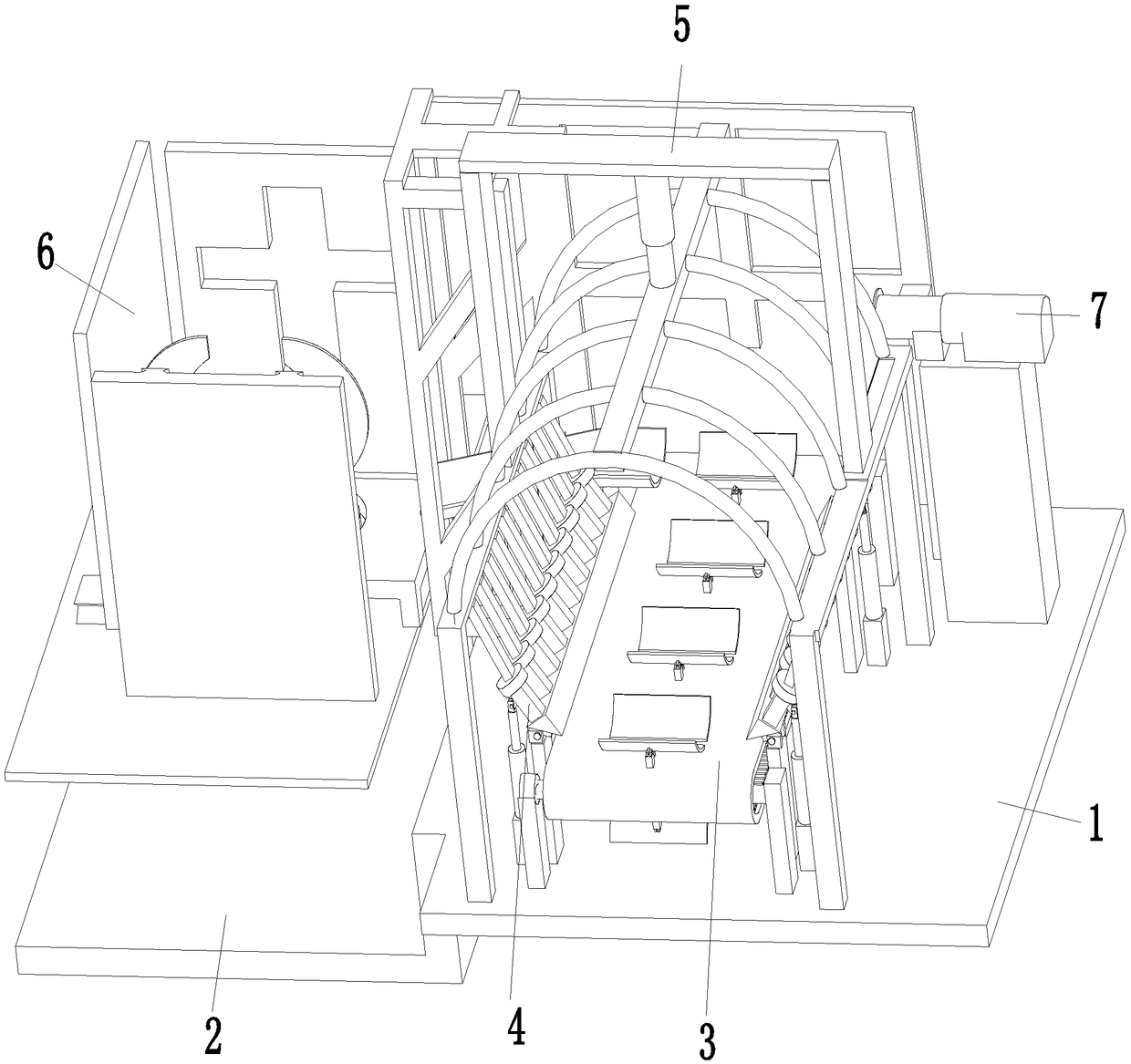
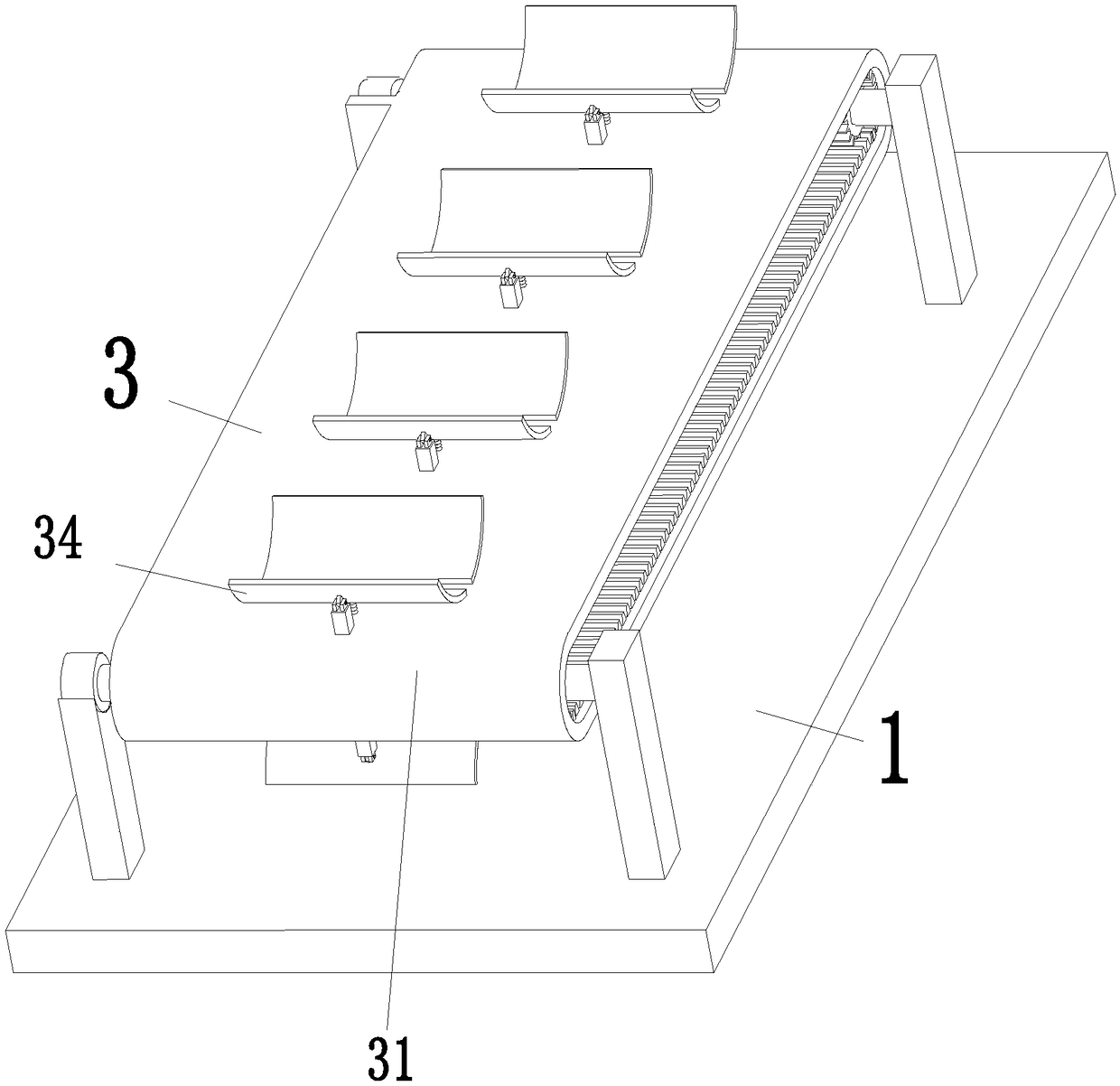
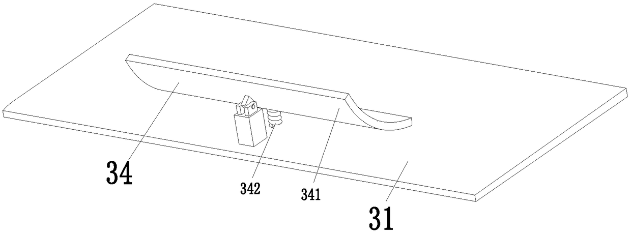
[0031] Such as Figure 1 to Figure 9 As shown, a waste tire threading transfer robot includes a No. 1 bottom plate 1, a No. 2 bottom plate 2, a transmission device 3, an auxiliary device 4, a limit device 5, an execution fixing device 6, and a pushing device 7. The bottom plate 2 is located at the lower left end of the No. 1 bottom plate 1. The lower left end of the No. 1 bottom plate 1 is fixedly connected to the upper right end of the No. 2 bottom plate 2. The transmission device 3 is installed on the middle of the upper end surface of the No. 1 bottom plate 1. The auxiliary device 4 is locat...


PUM


Abstract

The invention relates to a conveying robot for wire drawing of waste tires. The conveying robot comprises a first bottom plate, a second bottom plate, a conveying device, auxiliary devices, a limitingdevice, an executing fixing device and a pushing device, the conveying device is installed on the middle of the upper end surface of the first bottom plate, the auxiliary devices are symmetrically located on the two sides of the conveying device, the auxiliary devices are installed on the top of the first bottom plate, the limiting device is located right above the conveying device, the limitingdevice is installed on the top of the first bottom plate, the pushing device is installed on the rear side of the right end of the first bottom plate, the executing fixing device is located on the upper end surface of the middle of the second bottom plate, and the executing fixing device is connected with the second bottom plate. According to the conveying robot, the problems that fixing of the waste tires before wire drawing is performed is not firm, the assembly line type operation of wire drawing of the waste tires cannot be realized, steel wires on the other sides of the waste tires cannotbe continuously drawn after steel wires on one sides of the waste tires are drawn, and the waste tires cannot be fixed in the conveying process can be solved.

Description

Technical field [0001] The invention relates to the field of recycling and processing of automobile tires, and in particular to a waste tire spinning transmission robot. Background technique [0002] As one of the necessary parts of a car, tires should be replaced when they are used for two years or when the mileage reaches 60,000K. Otherwise, it will easily cause problems during the driving of the car, cause accidents, and threaten the lives of drivers. The replaced tires are generally treated as waste for recycling. Most of the existing recycling stations will send the waste tires to specific equipment for processing. The first thing that should be done is the toe wire of the tire toe protective layer. Snagging. [0003] Existing used tires are usually transferred manually before the wire drawing, and the wire drawing machine can only extract one side of the wire. If the other side of the wire needs to be drawn, the wire drawing machine needs to be suspended, and the used tires ...

Claims


Application Information

Patent Timeline
Patent Type & Authority Applications(China)
IPC IPC(8): B65G15/58B65G47/82B29B17/02
CPCB29B17/02B65G15/58B65G47/82B65G2201/0273Y02W30/62
Inventor 吴秋敏
Owner 安徽新博普曼智能科技股份有限公司
Why Eureka
Try Eureka