
Clamping robot for medical inspection equipment

A technology for medical testing equipment and robots, applied in the field of medical devices, can solve the problems of the parts connected to the testing equipment and the testing clips being easily damaged, affecting the accuracy of the testing results, and the clips being unusable, saving resources and reducing medical costs. , easy to use and fast effect

Inactive Publication Date: 2018-12-11
冯雪中
View PDF0 Cites 0 Cited by
  • Summary
  • Abstract
  • Description
  • Claims
  • Application Information

AI Technical Summary

Problems solved by technology

However, the existing medical testing equipment uses different medical testing clips for testing parameters of different parts of the human body. When it is necessary to test different parts of the human body, it is necessary to replace the testing clips corresponding to the parts, and often replace the testing clips The location will make the connecting part of the detection equipment and the detection clip vulnerable to damage, affecting the accuracy of the detection results. On the other hand, if a part of the clip is broken, the entire clip cannot be used and needs to be replaced with a new clip, resulting in a lot of waste.

Method used


Image

  • Clamping robot for medical inspection equipment
  • Clamping robot for medical inspection equipment
  • Clamping robot for medical inspection equipment

Examples


Embodiment Construction

[0024] The following will clearly and completely describe the technical solutions in the embodiments of the present invention with reference to the accompanying drawings in the embodiments of the present invention. Obviously, the described embodiments are only some, not all, embodiments of the present invention. Based on the embodiments of the present invention, all other embodiments obtained by persons of ordinary skill in the art without making creative efforts belong to the protection scope of the present invention.

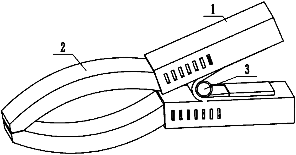
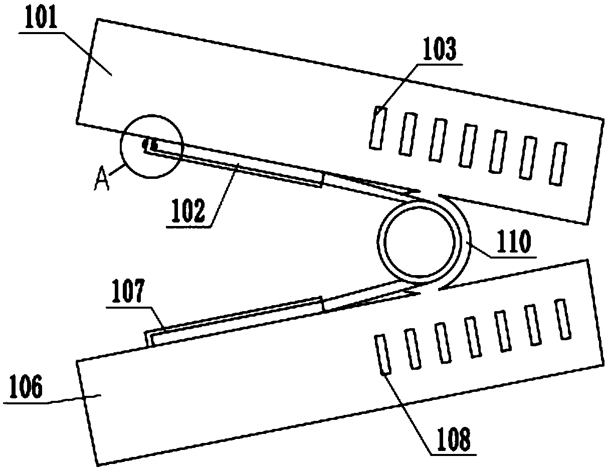
[0025] see Figure 1-6 As shown, a clamping robot for medical testing equipment in this embodiment includes a clamping seat 1, a chuck 2, and a spring splint 3. The clamping base 1 includes a pinch box one 101, a pinch box two 106, and a pinch box The lower end of one 101 and the upper end of pinch box two 106 are connected by spring guard 110, and the front end of pinch box one 101 is provided with jack one 104, and both sides of jack one 104 are all provided...


PUM


Abstract

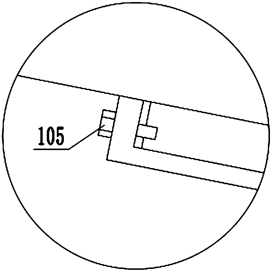
The invention discloses a clamping robot for medical inspection equipment. The robot comprises a clamping seat, a clamping head and a spring clamping plate, the clamping seat comprises a first pinching box and a second pinching box, the lower end of the first pinching box is connected with the upper end of the second pinching box through a spring protecting plate, the front end of the first pinching box is provided with a first inserting hole, first fixing holes are formed in the two sides of the first inserting hole, a first inserting plate box is arranged at the lower end of the first pinching box, the first inserting plate box is arranged on the left side of the spring protecting plate, the front and right ends of the first inserting plate box are of opening structures, a fixing bolt isarranged at the rear end of the first inserting plate box, the front end of the second pinching box is provided with a second inserting hole, second fixing holes are formed in the two sides of the second inserting hole, the second fixing holes correspond to the first fixing holes one by one, a second inserting plate box is arranged at the upper end of the second pinching box, the second insertingplate box is arranged on the left side of the spring protecting plate, the front and right ends of the second inserting plate box are of opening structures, the spring clamping plate is connected with the clamping seat through the first inserting plate box, the second inserting plate box and the spring protecting plates, and the clamping head is connected with the clamping seat through the firstand second inserting holes.

Description

technical field [0001] The invention relates to the field of medical equipment, in particular to a clamping robot used for medical detection equipment. Background technique [0002] Medical detection equipment uses medical detection clips to clamp the detected place to detect various parameters of the human body, and transmits the detection results to the central processor of the connected medical detection equipment for processing and analysis, thereby diagnosing various disease. However, the existing medical testing equipment uses different medical testing clips for testing parameters of different parts of the human body. When it is necessary to test different parts of the human body, it is necessary to replace the testing clips corresponding to the parts, and often replace the testing clips The location will make the part connected between the detection equipment and the detection clip vulnerable to damage, which will affect the accuracy of the detection results. On the ...

Claims


Application Information

Patent Timeline
IPC IPC(8): B25J15/00B25J11/00
CPCB25J15/00B25J11/00
Inventor 冯雪中
Owner 冯雪中
Learn More