Purifying machine with rapid and automatic water draining system and application method thereof

An automatic drainage and purifier technology, applied in the field of purifiers, can solve the problems of large installation space requirements, large operating noise, inconvenient installation, etc., to achieve the effect of convenient and fast installation, disassembly and maintenance, reducing the risk of blockage, and improving the user experience.

Active Publication Date: 2018-12-11
CHINA NAT FOOD PURIFICATION TECH BEIJING CO LTD
View PDF10 Cites 0 Cited by
  • Summary
  • Abstract
  • Description
  • Claims
  • Application Information

AI Technical Summary

Problems solved by technology

[0003] The purpose of the present invention is to provide a purification machine with a fast automatic drainage system and its use method, which solves the problem that the existing purification machine needs manual pouring or manual operation to place the drain pipe in the drainage pool for drainage. In addition, the artificial labor intensity of the user is increased, the technical problem of inconvenient user experience is brought to the user, and the installation process of the water catalyst generator in the existing purifier is complicated, and usually a connecting conductive part needs to be installed at least several small parts to complete the process. There are technical problems such as assembly, inconvenient installation and maintenance, many leaking points, and difficulty in sealing, as well as the technical problems of existing water pumps that require a large installation space, high operating noise, and difficult to clean dirt, as well as relying on physical rotation. Technical problems that are easy to cause damage to vulnerable objects in water

Method used


Image

  • Purifying machine with rapid and automatic water draining system and application method thereof
  • Purifying machine with rapid and automatic water draining system and application method thereof
  • Purifying machine with rapid and automatic water draining system and application method thereof

Examples


Embodiment Construction

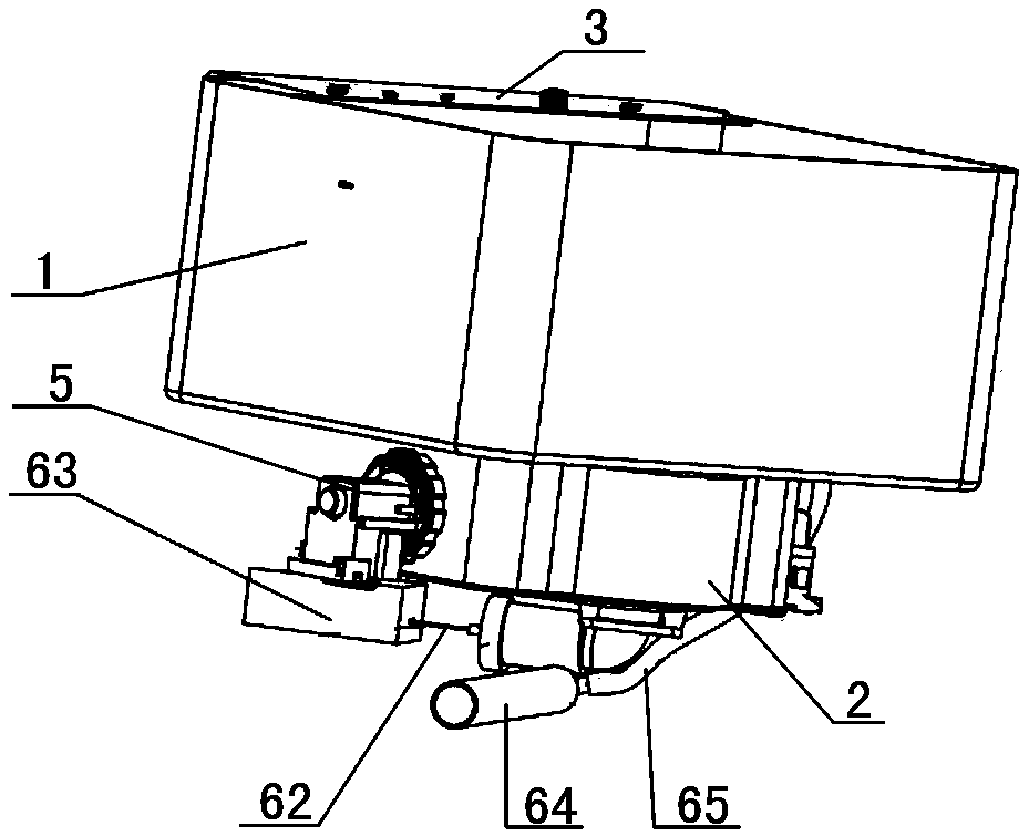
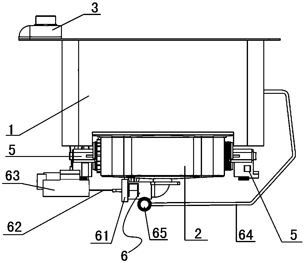
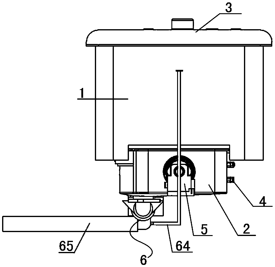
[0042] Hereinafter, embodiments of a purifier with a quick automatic drain system and a method of use thereof of the present invention will be described with reference to the accompanying drawings.

[0043] The examples described here are specific specific implementations of the present invention, and are used to illustrate the concept of the present invention. They are all explanatory and exemplary, and should not be construed as limiting the implementation of the present invention and the scope of the present invention. In addition to the embodiments described here, those skilled in the art can also adopt other obvious technical solutions based on the claims of the application and the contents disclosed in the description, and these technical solutions include adopting any obvious changes made to the embodiments described here. Replacement and modified technical solutions. The accompanying drawings in this specification are schematic diagrams, which assist in explaining the ...


PUM


Abstract

The invention relates to a purifying machine with a rapid and automatic water draining system and an application method thereof. The machine comprises a water tank, an operation panel, a purifying assembly and a water drainage assembly. The water drainage assembly comprises a water catalyst generator and lossless phase-change conduction water pumps. The water catalyst generator is vertically installed on a gate bin sidewall. The lossless phase-change conduction water pumps are installed on two sides of the water catalyst generator. The water drainage assembly is installed at a water drainage opening in the bottom of the water tank and comprises a water drainage valve and a tractor. A main water drainage opening of the water drainage valve is connected with a water drainage pipe. An overflow water drainage opening is connected with an overflow flexible pipe, the other end of which is installed in an overflow opening of the water tank. A traction buckle extending out of a tail end of thewater drainage valve is connected with a traction rope of the tractor. A control wiring terminal of the tractor is electrically connected with the operation panel. The machine is equipped with an automatic water draining system. While a basic water drainage function is fulfilled, automatic water drainage is achieved. Additionally, water draining efficiency is substantially raised. Labor intensityof a user is reduced. More selections are provided for the user. User experience is improved.

Description

technical field [0001] The invention belongs to the technical field of purifiers, and in particular relates to a purifier with a fast automatic drainage system and a use method thereof. Background technique [0002] At present, most of the common food purifiers or cleaning machines in the market do not have the automatic drainage function, and still require manual pouring or manual operation to place the drainpipe into the drainage pool for drainage. These drainage methods increase the number of users to a certain extent. The artificial labor intensity, in today's rapid development of automation, brings users an inconvenient experience. In addition, although the overall structure of the existing water catalyst generator and water pump is simple, the installation process of the water catalyst generator is complicated. Usually, at least a few small parts need to be installed on a connecting conductive part to complete the assembly, which is not easy to install, maintain and le...

Claims


Application Information

Patent Timeline
Patent Type & Authority Applications(China)
IPC IPC(8): A23N12/02A47J43/24
CPCA23N12/02A47J43/24
Inventor 谭燕牟澜白云光
Owner CHINA NAT FOOD PURIFICATION TECH BEIJING CO LTD
Why Eureka
Try Eureka