engine starter
An engine starting and engine technology, which is applied to the starting of the engine, the power unit, the starting of the motor for the engine, etc. Effect
- Summary
- Abstract
- Description
- Claims
- Application Information
AI Technical Summary
Problems solved by technology
Method used
Image


Examples
Embodiment approach 1
[0050] figure 1 It is a block diagram showing a schematic configuration of a vehicle equipped with the engine starting device according to Embodiment 1 of the present invention. exist figure 1 Among them, the engine 1 includes a function of judging engine stop or engine restart in automatic engine stop and restart control, and the engine 1 is controlled by an engine control device 5 for drive control. Hereinafter, the engine control device 5 is referred to as an engine ECU 5 .
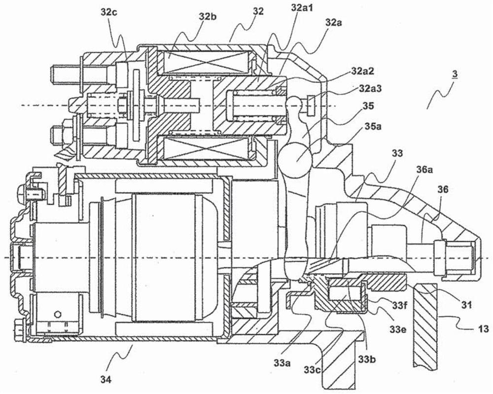
[0051] A generator motor 2 is always connected to a crankshaft 11 of the engine 1 via a belt 12 . In addition, the pinion gear 31 serving as an output portion of the rotational torque of the starter 3 is detachably provided on the ring gear 13 integrated with the crankshaft 11 , and transmits rotational torque.
[0052] A power conversion device 21 is connected to the generator motor 2 . Furthermore, the power conversion device 21 is connected to the storage battery 4 and a generator motor control ...
Embodiment approach 2
[0091] In Embodiment 2 of the present invention, the function of the one-way clutch 33 of the starter 3 will be described.
[0092] In the above first embodiment, in the combined cranking, the generator motor 2 and the starter 3 crank the engine 1 at the same time, and each air cylinder of the engine 1 repeatedly performs the steps of intake→compression→expansion→exhaust. During the expansion stroke, the load becomes larger, and during the expansion stroke, the load becomes smaller. Therefore, fluctuations in which the cranking rotation speed repeatedly decreases and increases occur.
[0093] In addition, in the generator motor 2 connected to the crankshaft 11 by the belt 12 , the speed reduction ratio between the output shaft of the generator motor 2 and the crankshaft 11 of the engine 1 is about 2 to 3. In addition, the starter 3 detachably connected by gears has a reduction mechanism with a reduction ratio of about 4 to 6 inside the starter 3, and the reduction ratio of th...
Embodiment approach 3
[0112] In the above-mentioned second embodiment, the method of adjusting the idle torque of the one-way clutch 33 in order to suppress the rotation speed on the high rotation side of the cranking fluctuation was described, but in the third embodiment of the present invention, the method for obtaining and implementing A method of reducing the output torque of the generator motor 2 with the same effect as the method 2 will be described.
[0113] In addition, the configuration and the series of operations for starting the engine in Embodiment 3 are the same as those in Embodiment 1 described above. In addition, in the combined cranking according to Embodiment 3 of the present invention, it is characterized in that the output torque of the generator motor 2 is reduced from the initial stage to implement the cranking.
[0114] In conventional engine start-ups, extreme low temperatures such as -30°C were also taken into consideration, but output restrictions were seldom set for shor...
PUM
 Abstract
Description
Claims
Application Information
 - R&D
- Intellectual Property
- Life Sciences
- Materials
- Tech Scout
- Unparalleled Data Quality
- Higher Quality Content
- 60% Fewer Hallucinations
Browse by: Latest US Patents, China's latest patents, Technical Efficacy Thesaurus, Application Domain, Technology Topic, Popular Technical Reports.
© 2025 PatSnap. All rights reserved.Legal|Privacy policy|Modern Slavery Act Transparency Statement|Sitemap|About US| Contact US: help@patsnap.com