


Quick Research
Generate reliable direction feasibility study reports for your R&D in just a few steps.

Technical Q&A
Discover and master advanced knowledge NOW. Basics, ideas, possibilities, all at once.

Find Solutions
As an expert in R&D theories, this can generate solutions to your technical problems instantly.

Evaluate Feasibility
Analyze your overall solution with one click, know your potential R&D risks in advance.

Monitor Landscape
Get weekly tech updates, stay abreast of the latest tech innovations and key insights.
Electronic equipment display frame
A technology for electronic equipment and display racks, applied in display hangers, display shelves, display stands, etc., can solve problems such as low utilization rate, single structure of display racks, inability to display products in all directions, and achieve simple structure and convenient maintenance Effect
- Summary
- Abstract
- Description
- Claims
- Application Information
AI Technical Summary
Problems solved by technology
Method used
Image


Examples
Embodiment 1
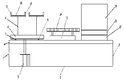
[0027] Such as Figure 1-3 As shown, the technical solution of the present invention is: an electronic equipment display rack, comprising a left plate 1, a right plate 2, a bottom plate 3 and a top plate 4, and the upper surface of the top plate 4 is sequentially provided with a first placement mechanism from left to right , the second placement mechanism and the third placement mechanism,
[0028] The first placement mechanism includes a placement motor 5, the placement motor 5 is arranged on the upper surface of the bottom plate 3, the output shaft of the placement motor 5 passes through the motor perforation on the top plate 4, and is connected with the rotating horizontal plate 6 The lower surface of the left and right sides of the lower end of the rotating horizontal plate 6 is connected to the upper end of the left rotating rod 7 and the right rotating rod 8 respectively, and the left rotating rod 7 and the right rotating rod 8 The lower end of the lower end is respecti...
Embodiment 2
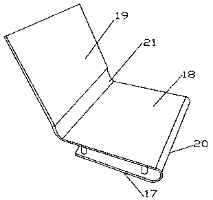
[0036] The lower surface of the upper arc-shaped plate 14 is arranged on the upper surface of the top plate 4 through the left and right adjustment parts. The left and right adjustment parts have the same structure, and the left adjustment part includes a lower adjustment rod, an upper sleeve tube, the lower end of the lower adjusting rod is set on the top plate 4, the upper end of the lower adjusting rod is sleeved in the upper sleeve, and the upper end of the upper sleeve is set on the lower surface of the upper arc plate 14, An adjustment hole is provided on the upper casing, and the bolt passes through the adjustment hole, and is supported on the outer wall of the lower adjustment rod; when various notebook structures can be displayed separately, multiple third placement mechanisms are provided on the top plate 4 .
[0037] The working process of this example: When in use, place the earphones and pendants on the left and right hanging parts separately, place the electronic ...
PUM
 Abstract
Description
Claims
Application Information
 - R&D Engineer
- R&D Manager
- IP Professional
- Industry Leading Data Capabilities
- Powerful AI technology
- Patent DNA Extraction
Browse by: Latest US Patents, China's latest patents, Technical Efficacy Thesaurus, Application Domain, Technology Topic, Popular Technical Reports.
© 2024 PatSnap. All rights reserved.Legal|Privacy policy|Modern Slavery Act Transparency Statement|Sitemap|About US| Contact US: help@patsnap.com