Shock absorption base for building engineering equipment

A technology for construction engineering and equipment, applied in shock absorbers, mechanical equipment, springs/shock absorbers, etc. Stable and reliable effect, improved applicability, and efficient shock absorption

Inactive Publication Date: 2018-12-04
文芙生
View PDF0 Cites 13 Cited by
  • Summary
  • Abstract
  • Description
  • Claims
  • Application Information

AI Technical Summary

Problems solved by technology

[0003] In the process of building production and construction, some mechanical equipment is often used. However, there are still some deficiencies in the existing shock-absorbing bases of construction engineering equipment. Connected installation, the applicability is not wide, on the other hand, the shock absorption capacity is limited, and when the mass of construction engineering equipment is large or the vibration effect is large, it cannot play an effective shock absorption effect

Method used


Image

  • Shock absorption base for building engineering equipment
  • Shock absorption base for building engineering equipment
  • Shock absorption base for building engineering equipment

Examples


Embodiment 1

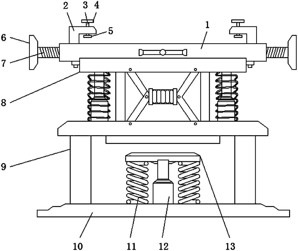
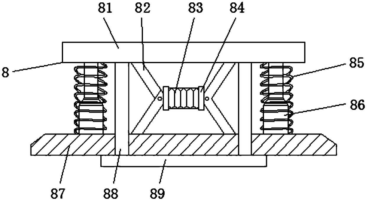
[0025] Embodiment one, with reference to Figure 1-2 , a shock absorbing base for construction engineering equipment, comprising a base plate 1, characterized in that the bottom of the base plate 1 is fixedly connected with a shock absorbing mechanism 8, and the shock absorbing mechanism 8 is composed of a top plate 81, a connecting rod 82, an air spring 83, and a connecting block 84 , the first damping spring 85, the first hydraulic telescopic rod 86, the bottom plate 87, the pole 88 and the upper contact plate 89 are combined, the two ends of the air spring 83 are connected with the connecting block 84, and the upper and lower ends of the connecting block 84 They are respectively hinged with the top plate 81 and the bottom plate 87 through connecting rods 82, and the bottom sides of the top plate 81 are connected with the top sides of the bottom plate 87 through symmetrically arranged first hydraulic telescopic rods 86, and the outer sides of the first hydraulic telescopic ro...

Embodiment 2

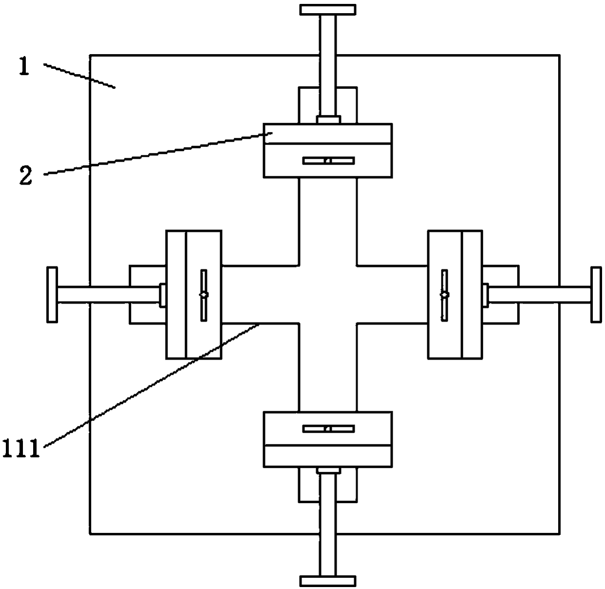
[0026] Embodiment two, refer to figure 1 with image 3 , the inside of the substrate 1 is provided with a convex chute 111 in a cross shape, and the inside of the convex chute 111 is slidably connected with a convex slider 14, and the center of one side of the convex slider 14 is movably connected with a second fixed bearing. Threaded rod 7, and the second threaded rod 7 runs through one side of the substrate 1 and is welded with the second screw rod 6. The top of the convex chute 111 is welded with an L-shaped clamping plate 2, and the convex shape is made by rotating the second screw rod 6. The slider 14 slides inside the convex chute 111, and the convex slider 14 drives the L-shaped clamping plate 2 to limit the side of the connection seat of the construction equipment, thereby satisfying the installation and use of construction equipment of different sizes.

Embodiment 3

[0027] Embodiment three, refer to figure 1 The horizontal end of the L-shaped clamp 2 is vertically screwed and connected with the first threaded rod 3, the top of the first threaded rod 3 is welded with the first screw 4, and the bottom end is welded with the lower side of the horizontal end of the L-shaped clamp 2. The spacer 5 rotates the first screw rod 4 and the first threaded rod 3 rotates, so that the spacer 5 goes down, and finally limits the top of the construction equipment connection seat, so that the fixing effect is more stable and reliable.


PUM


Abstract

The invention discloses a shock absorption base for building engineering equipment. The shock absorption base comprises a substrate, wherein the bottom of the substrate is fixedly connected to a shockabsorption mechanism; the shock absorption mechanism is formed by combining a carrier plate, connecting rods, an air spring, a connecting block, first shock absorption springs, first hydraulic expansion links, a baseplate, a supporting rod and an upper contact plate; the two ends of the air spring are connected to the connecting block; the upper end and lower end of one side of the connecting block are respectively articulated with the carrier plate and the baseplate through the connecting rods; the two sides of the bottom of the carrier plate are connected to the two sides of the top of thebaseplate through the first hydraulic expansion links which are symmetrically arranged; and the outer sides of the first hydraulic expansion links are in sleeve connection with the first shock absorption springs. Under the action of vibration, the carrier plate is stressed to run downwards, thereby enabling the connecting rods to be angularly deflected, at the moment, the air spring is compressed,absorbs shock and is matched with the first shock absorption springs to absorb and neutralize the vibration effect, and thereby, the high-efficiency shock absorption effect is achieved.

Description

technical field [0001] The invention relates to the technical field of construction engineering equipment, in particular to a shock-absorbing base for construction engineering equipment. Background technique [0002] Building construction refers to the production activities in the implementation stage of engineering construction. It is the construction process of various buildings. It can also be said to be the process of turning various lines on the design drawings into physical objects at designated locations. It includes basic engineering construction. , main structure construction, roofing engineering construction, decoration engineering construction, etc., the place of construction work is called "building construction site" or "construction site", also called construction site. [0003] In the process of building production and construction, some mechanical equipment is often used. However, there are still some deficiencies in the existing shock-absorbing bases of cons...

Claims


Application Information

Patent Timeline
IPC IPC(8): F16M5/00F16F7/00
CPCF16M5/00F16F7/00
Inventor 文芙生
Owner 文芙生
Why Eureka
Try Eureka