Impeller structure used for compressor or air blower
A technology for blowers, compressors, used in parts of pumping devices for elastic fluids, machines/engines, mechanical equipment, etc.
- Summary
- Abstract
- Description
- Claims
- Application Information
AI Technical Summary
Problems solved by technology
Method used
Image
Examples
Embodiment Construction
[0018] The present invention will be described in further detail below in conjunction with the accompanying drawings.
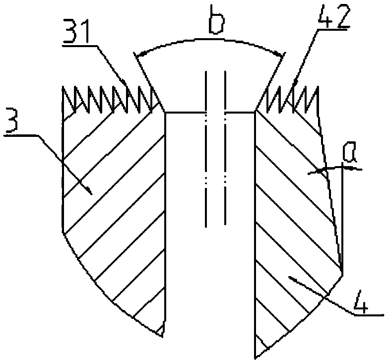
[0019] See attached Figure 1-3 : The impeller structure for a compressor or blower includes a shaft 1, a first diameter section 11, a second diameter section 12, a blade 2, a leading edge 21, a trailing edge 22, a front disc 3, a toothed seal 31, and a rear disc 4 , Rear disk sealing ring 41, tooth seal 42, bypass channel 43, wheel hub 5, arc section 51, arc nut 6, threaded connector 7.
[0020] The rotor includes a rotating shaft 1 and an impeller. The rotating shaft 1 sequentially includes a first diameter section 11 and a second diameter section 12 whose diameters are successively reduced; The outer circumference of the threaded connector 7 has an external thread, one end of the threaded connector 7 is screwed with the second diameter section 12, and this end is screwed into the internal thread hole of the second diameter section 12, and the other end of ...
PUM
 Abstract
Description
Claims
Application Information
 - Generate Ideas
- Intellectual Property
- Life Sciences
- Materials
- Tech Scout
- Unparalleled Data Quality
- Higher Quality Content
- 60% Fewer Hallucinations
Browse by: Latest US Patents, China's latest patents, Technical Efficacy Thesaurus, Application Domain, Technology Topic, Popular Technical Reports.
© 2025 PatSnap. All rights reserved.Legal|Privacy policy|Modern Slavery Act Transparency Statement|Sitemap|About US| Contact US: help@patsnap.com


