Landing apron for unmanned aerial vehicle

A technology for parking apron and drones, applied in the field of drones, can solve the problems of low work efficiency of drones, inability to meet the charging of multiple drones at the same time, and inconvenient charging and maintenance process of drones.

Inactive Publication Date: 2018-12-04
EWATT TECH CO LTD
View PDF0 Cites 1 Cited by
  • Summary
  • Abstract
  • Description
  • Claims
  • Application Information

AI Technical Summary

Problems solved by technology

[0005] The technical problem to be solved by the present invention is that the charging and maintenance process of the UAV is inconvenient, and the work efficiency of the UAV is low;

Method used


Image

  • Landing apron for unmanned aerial vehicle
  • Landing apron for unmanned aerial vehicle
  • Landing apron for unmanned aerial vehicle

Examples


Embodiment approach

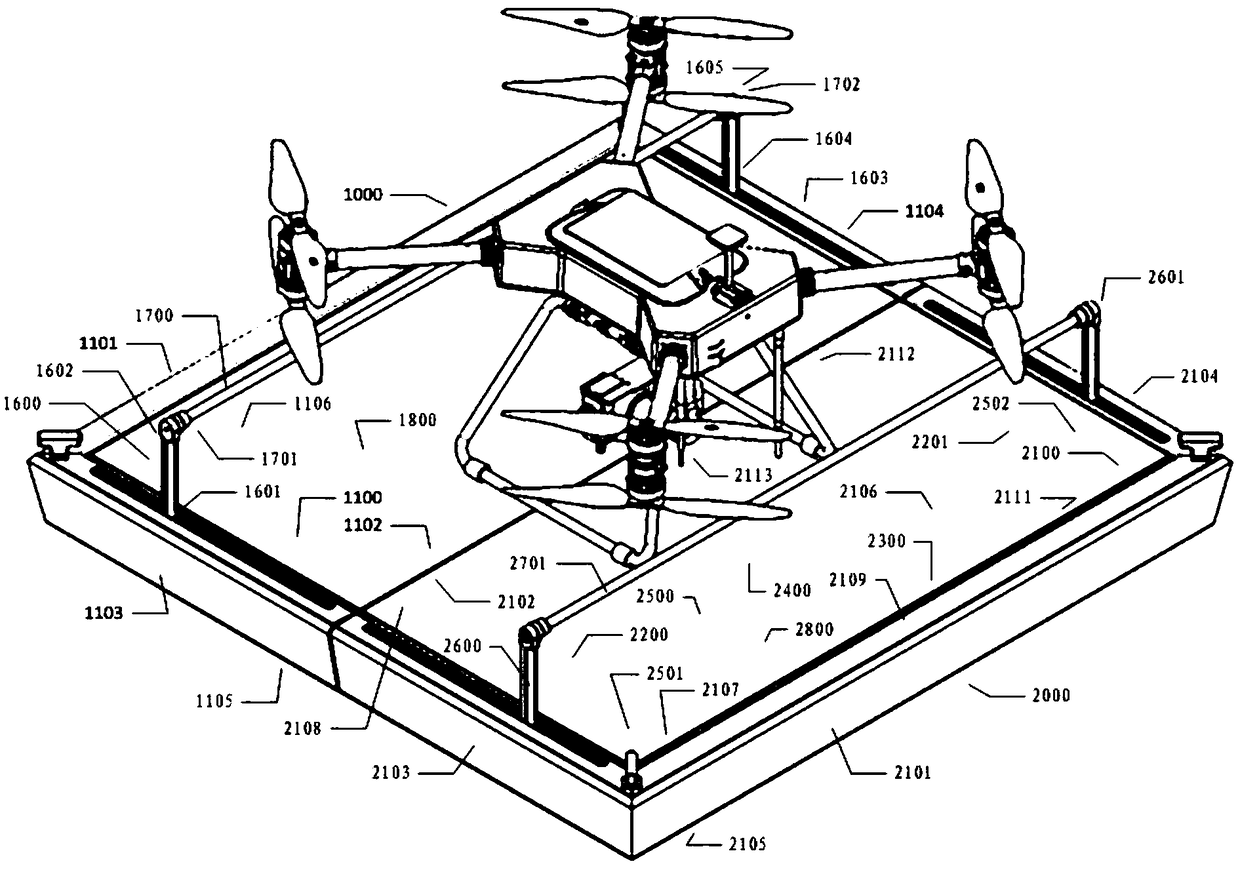
[0033] Please continue to see figure 1 and Figure 4 , figure 1 It is a schematic diagram of the overall structure of a charging device for drones provided by an embodiment of the present invention, Figure 4It is a structural schematic diagram of the first apron for a charging device for drones provided by an embodiment of the present invention. In order to explain in detail that the first supporting end 1601 of the first supporting arm 1600 can be hinged to the first limiting area 1505 of the first moving end 1501 in the first base 1500, the following two implementation modes are provided for detailed description: The first implementation. When the second support end 1602 drives the first electrode rod 1700 to gradually move toward the first bottom surface 1105, the first support arm 1600 can move to a position perpendicular to the first electrode plate 1800, which is the first support The position of the arm 1600 during normal operation. At the same time, when the firs...


PUM


Abstract

The invention discloses a landing apron for an unmanned aerial vehicle and belongs to the technical field of unmanned aerial vehicles. The landing apron for the unmanned aerial vehicle comprises a second apron, a third apron, a fourth apron and a landing frame. The second apron comprises a third guide rail, a fourth guide rail, a second lead screw, a second base, a third supporting arm, a fourth supporting arm, a second electrode rod and a second electrode plate; the third apron comprises a third lead screw, a third base, a fifth supporting arm, a third electrode rod, a third electrode plate and a second control part; and the fourth apron comprises a seventh guide rail, an eighth guide rail, a fourth lead screw, a fourth base, a seventh supporting arm, an eighth supporting arm, a fourth electrode rod and a fourth electrode plate. The landing frame comprises a first foot stool, a second foot stool, a third foot stool, a fourth foot stool and a support. According to the landing apron forthe unmanned aerial vehicle, the charging maintenance process of the unmanned aerial vehicle is convenient, the working efficiency of the unmanned aerial vehicle is enhanced, and a technical effect that the multiple unmanned aerial vehicles are simultaneously charged can be satisfied.

Description

technical field [0001] The invention belongs to the technical field of unmanned aerial vehicles, and in particular relates to a landing apron for unmanned aerial vehicles. Background technique [0002] Unmanned UAV, referred to as "UAV", is an unmanned UAV controlled by radio remote control equipment and its own program control device. There is no cockpit on board, but it is equipped with autopilot, program control device, information collection device and other equipment. The personnel on the ground, on the ship, or at the remote control station of the parent aircraft track, locate, remotely control, telemeter and digitally transmit it through radar and other equipment. It can take off like an ordinary UAV under radio remote control or be launched into the air with a booster rocket, or it can be brought into the air by the parent aircraft for flight. UAVs are often used for inspections of mountainous areas and transmission lines across large rivers, as well as line inspec...

Claims


Application Information

Patent Timeline
IPC IPC(8): B64F1/00B60L11/18
CPCB64F1/00B60L2200/10
Inventor 不公告发明人
Owner EWATT TECH CO LTD
Why Eureka
Try Eureka