
Robot end executor and robot

An end effector and robot technology, applied in the field of robots, can solve problems such as reducing work efficiency and increasing operating costs, and achieve the effect of reducing operating costs and improving operating efficiency.

Pending Publication Date: 2018-12-04
SIASUN CO LTD
View PDF6 Cites 7 Cited by
  • Summary
  • Abstract
  • Description
  • Claims
  • Application Information

AI Technical Summary

Problems solved by technology

However, the use of two robots to grab the workpiece greatly increases the operating cost, and the replacement of the end effector to grab the workpiece not only increases the operating cost, but also reduces the work efficiency

Method used


Image

  • Robot end executor and robot
  • Robot end executor and robot
  • Robot end executor and robot

Examples


Embodiment Construction

[0020] The technical solutions of the present invention will be further described below in conjunction with the accompanying drawings and through specific implementation methods. It should be understood that the specific embodiments described here are only used to explain the present invention, but not to limit the present invention. In addition, it should be noted that, for the convenience of description, only some structures related to the present invention are shown in the drawings but not all structures.

[0021] In describing the present invention, it should be understood that the terms "center", "longitudinal", "transverse", "upper", "lower", "front", "rear", "left", "right", " The orientations or positional relationships indicated by "vertical", "horizontal", "top", "bottom", "inner", "outer", etc. are based on the orientation or positional relationships shown in the drawings, and are only for the convenience of describing the present invention and simplifying Describe...


PUM


Abstract

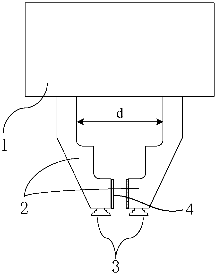
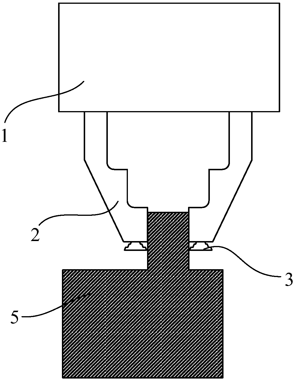
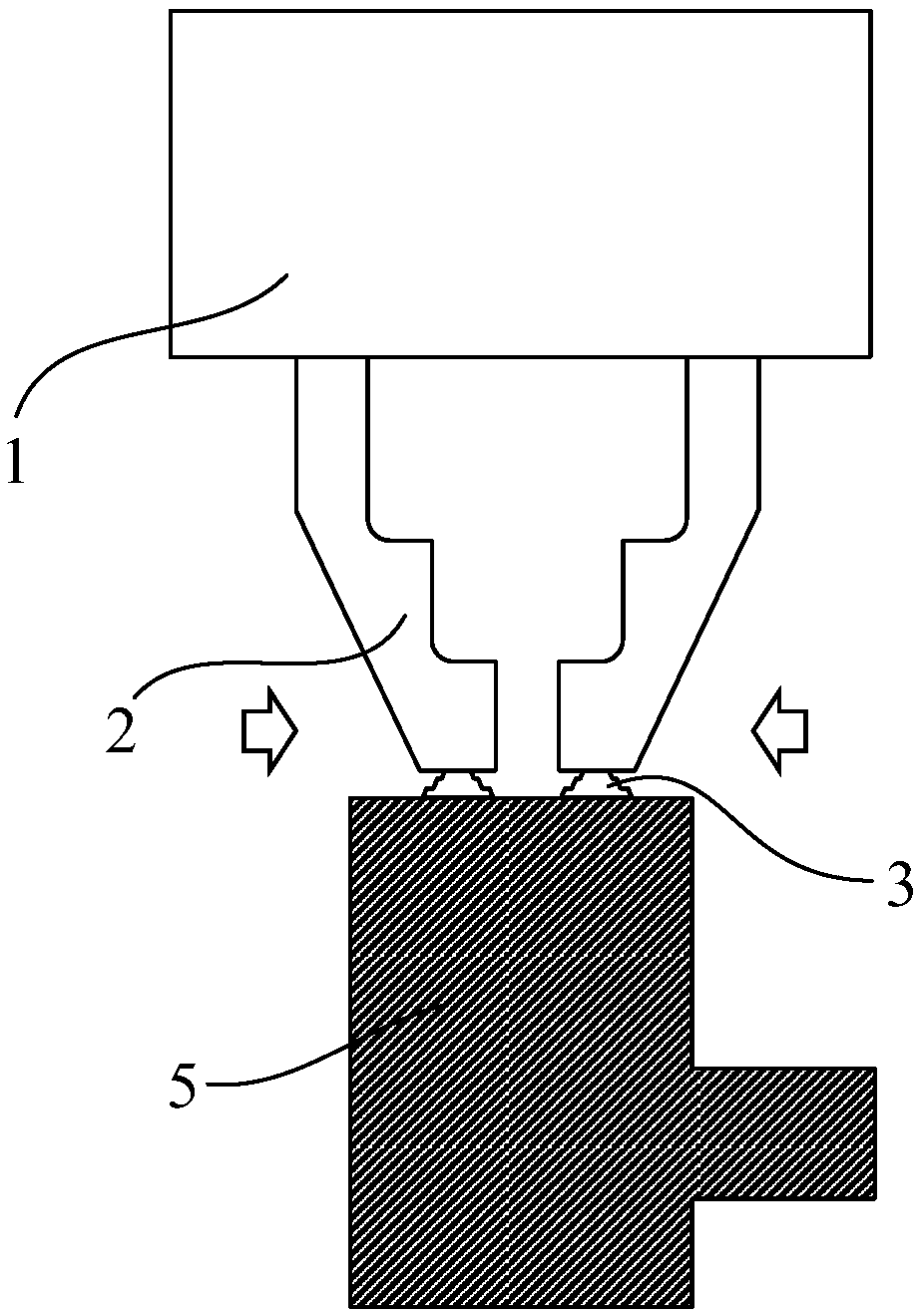
The invention discloses a robot end executor and a robot. The robot end executor comprises an end executor body, at least one pair of clamping jaws and at least one sucking cup. The at least one pairof clamping jaws are arranged on the end executor body and are used for clamping workpieces, and the interval between each pair of clamping jaws is adjustable. The at least one sucking cup is fixed tothe bottom of corresponding clamping jaw and is used for sucking the workpieces. By means of the robot end executor and the robot, the work cost is lowered, and work efficiency is improved.

Description

technical field [0001] Embodiments of the present invention relate to the technical field of robots, and in particular to a robot end effector and a robot. Background technique [0002] With the development of science and technology, robots have been widely used in many fields, such as machinery manufacturing, electronic technology, agricultural picking and demolition operations, etc. The control of robot movements is realized through sensors, cameras and control devices. Work that requires a lot of manpower to complete. [0003] The handling and palletizing of workpieces requires the end effector of the robot to achieve. Generally, end effectors include jaw actuators and suction cup actuators, and different end effectors are selected according to the grasping type applicable to the workpiece. In the process of workpiece handling and stacking, in order to realize the grasping of workpieces of different grasping types, robots with gripper actuators and robots with suction c...

Claims


Application Information

Patent Timeline
Patent Type & Authority Applications(China)
IPC IPC(8): B25J15/08B25J15/06
CPCB25J15/0616B25J15/08
Inventor 左方睿陈宏伟刘雪梅
Owner SIASUN CO LTD
Learn More