Electrodes for resistance welding

A resistance welding and electrode technology, applied in resistance welding equipment, electrode characteristics, welding equipment, etc., can solve the problems of wasting compressed air, high maintenance cost, not so economical, etc., and achieve the effect of reducing gas consumption and reducing the possibility of movement

Active Publication Date: 2021-02-02
DOCERAM
View PDF8 Cites 0 Cited by
  • Summary
  • Abstract
  • Description
  • Claims
  • Application Information

AI Technical Summary

Problems solved by technology

This has the disadvantage that compressed air is wasted on the one hand, which makes the method less economical
[0008] However, the control electronics are complex and expensive, and the maintenance effort is high

Method used


Image

  • Electrodes for resistance welding
  • Electrodes for resistance welding
  • Electrodes for resistance welding

Examples


Embodiment Construction

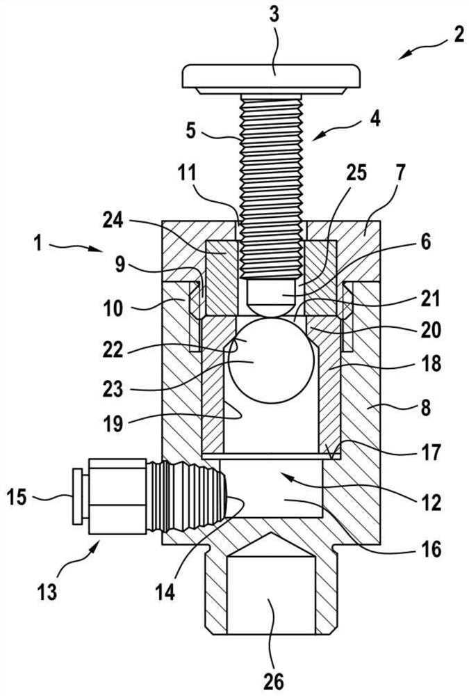
[0051] figure 1 An exemplary embodiment of an electrode 1 according to the invention is shown in a schematic sectional view. It should be pointed out that in the following description of the figures, components having the same or similar function are provided with the same reference symbols for reasons of clarity, even if the components deviate from one another in detail. Positional specifications such as "above", "below", "sideways" or "rearward" relate to the upright electrode 1 as it is used and depicted in resistance welding.

[0052] Shown are electrode 1 and plug 2 . The bolt 2 is currently designed as a bolt. The bolt has a bolt head 3 and a bolt shank 4 which is directly connected to the bolt head 3 .

[0053] The bolt shank 4 has a thread 5 . The thread 5 is formed as an external thread. Furthermore, the screw shank 4 has a free end 6 . The free end 6 is tapered on the end side. Bolts are currently made of metal, especially steel.

[0054] The electrode 1 has ...


PUM


Abstract

The invention relates to an electrode for resistance welding studs, which has an upper part (7) and a lower part (8), which are designed to be connected to one another and together provide a space in the connected state. A chamber (12), wherein the upper part has an opening (11) for introducing a plug and the lower part has a gas connection for gas under pressure. A valve body (23) is arranged in the cavity (12), by which the opening (11) can be closed. Thus, the applied compressed air is prevented from flowing out. Compressed air flows out only when the valve body (23) releases said opening (11).

Description

technical field [0001] The invention relates to an electrode for a resistance welding stud, which has an upper part and a lower part, which are designed to be connected to one another and together provide a cavity in the connected state, wherein the upper part has Openings for inserting plugs, and the lower part has a gas connection for gas under pressure. Background technique [0002] Methods for resistance welding bolts to sheet metal are sufficiently known in the prior art. An electrode is used here, which provides a cavity and access in the form of an opening for the plug. Here, a typical bolt has a head and a shaft. The head is intended to be supported on a metal sheet. The head is welded to the sheet metal. The rod can be formed smoothly or have an external or internal thread. [0003] For welding the studs to the sheet metal, resistance welding is used, for example. Here, the metal sheet is placed on the upper part of the electrode. The pin is inserted with its...

Claims


Application Information

Patent Timeline
Patent Type & Authority Patents(China)
IPC IPC(8): B23K11/30F16K1/14F16K27/02
CPCB23K11/30F16K1/14F16K27/0245B23K11/0053B23K11/14B23K11/36B23K11/3009
Inventor T·菲德雷尔C·丁佩尔曼
Owner DOCERAM
Why Eureka
Try Eureka