
Electronic terminal

An electronic terminal and sub-tube technology, applied in electrical components, sensors, loudspeakers, etc., can solve the problems of high volume attenuation, affecting user experience, low loudness of electronic terminals, etc., to improve sound reliability and sound loudness. Effect

Pending Publication Date: 2018-11-30
GOERTEK INC
View PDF0 Cites 7 Cited by
  • Summary
  • Abstract
  • Description
  • Claims
  • Application Information

AI Technical Summary

Problems solved by technology

However, when the sound emitted by the sound emitting device is transmitted in the sound guide tube, a large volume attenuation usually occurs, which leads to a low loudness of the electronic terminal and affects the user experience.

Method used


Image

  • Electronic terminal
  • Electronic terminal
  • Electronic terminal

Examples


Embodiment Construction

[0031] The technical solutions in the embodiments of the present invention will be clearly and completely described below in conjunction with the accompanying drawings in the embodiments of the present invention. Obviously, the described embodiments are only a part of the embodiments of the present invention, rather than all the embodiments. Based on the embodiments of the present invention, all other embodiments obtained by those of ordinary skill in the art without creative work shall fall within the protection scope of the present invention.

[0032] It should be noted that if there is a directional indication (such as up, down, left, right, front, back...) in the embodiment of the present invention, the directional indication is only used to explain that it is in a specific posture (as shown in the drawings). If the specific posture changes, the relative positional relationship, movement, etc. of the components below will also change the directional indication accordingly.

[0...


PUM


Abstract

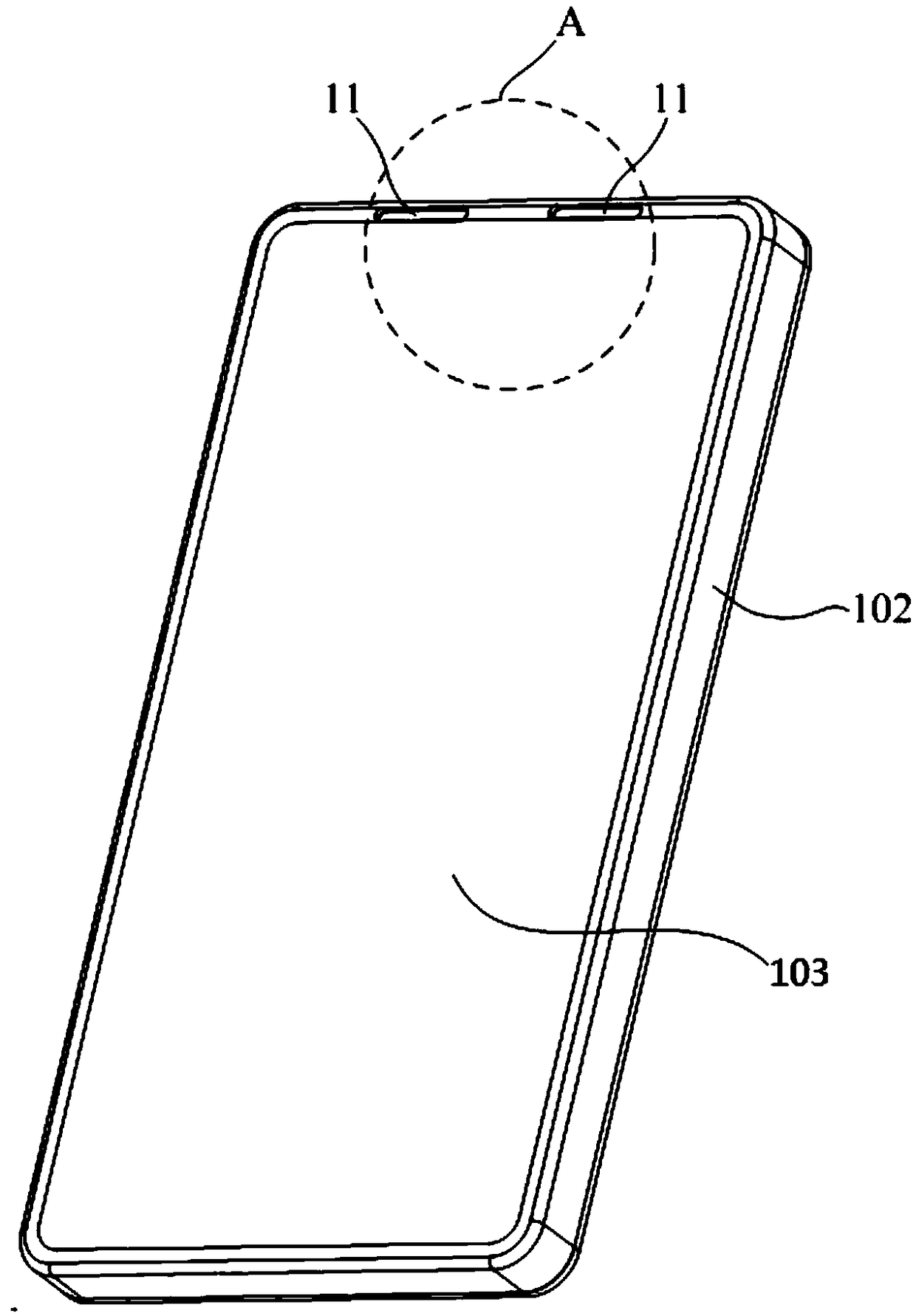
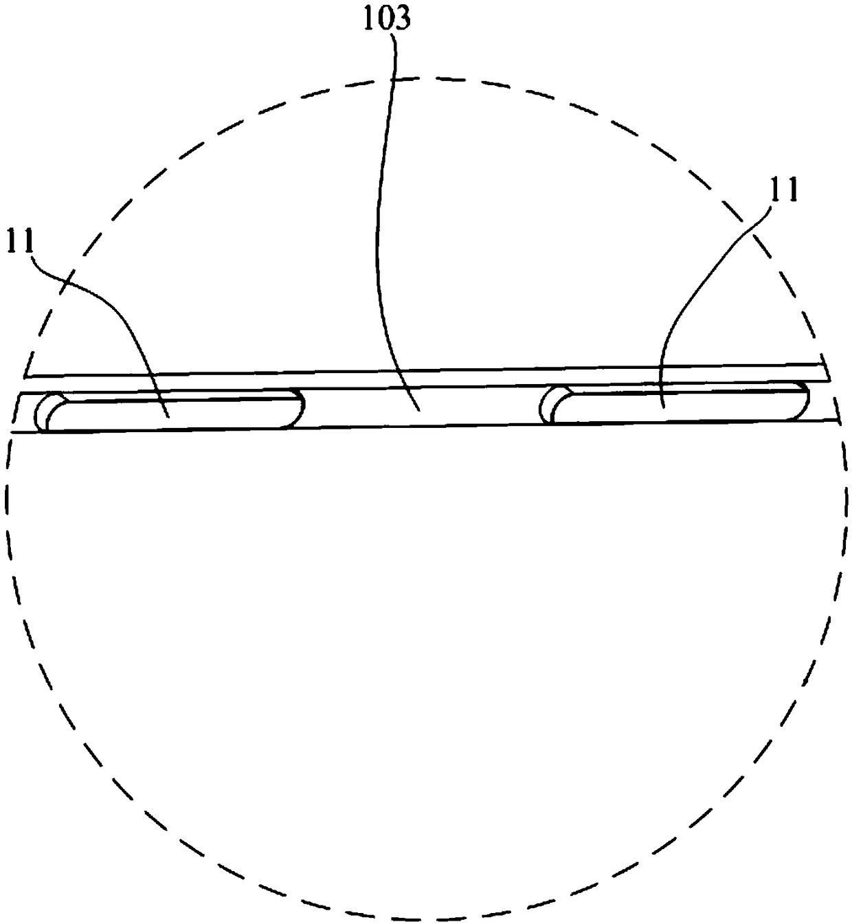
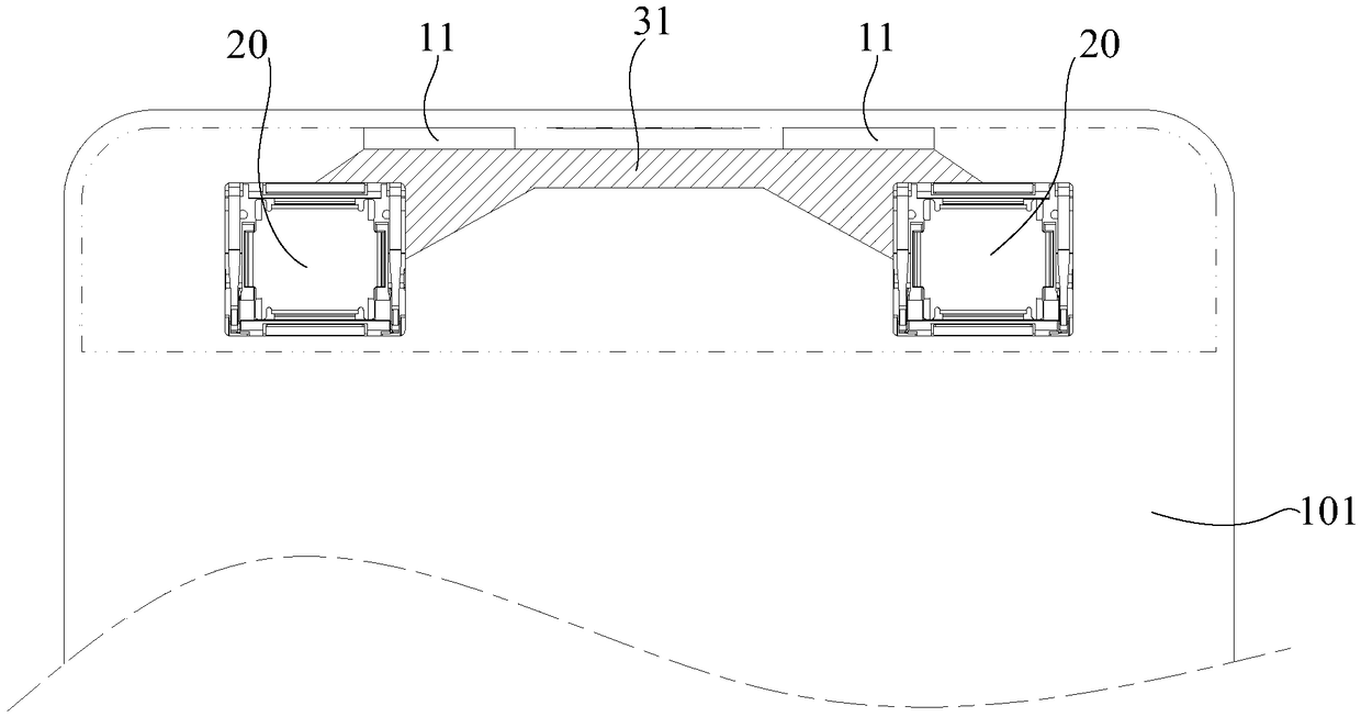
The invention discloses an electronic terminal comprising a shell provided with at least two sound outlets; at least two sound emission devices arranged in the shell, wherein each sound emission device is arranged to be corresponding to one sound outlet; and a sound guiding tube structure communicating the corresponding sound emission device and sound outlet. According to the technical scheme provided by the invention, the sound loudness of the electronic terminal can be improved.

Description

Technical field [0001] The present invention relates to the technical field of electronic terminals, in particular to an electronic terminal. Background technique [0002] In existing electronic terminals (such as but not limited to mobile phones, IPADs, etc.), usually only one sound emitting device is provided inside, and the sound emitting device is connected with a sound hole on the electronic terminal housing through a sound guide tube to export sound. However, when the sound emitted by the sound emitting device is conducted in the sound guide tube, a large volume attenuation usually occurs, which results in a low loudness of the electronic terminal and affects user experience. Summary of the invention [0003] The main purpose of the present invention is to provide an electronic terminal, which aims to improve the sound loudness of the electronic terminal. [0004] In order to achieve the above objectives, the electronic terminal proposed by the present invention includes: [0...

Claims


Application Information

Patent Timeline
IPC IPC(8): H04R9/06H04R9/02
CPCH04R9/02H04R9/06H04R2400/11
Inventor 蔡晓东马江羽
Owner GOERTEK INC
Learn More