
Optical fiber fault monitoring and accurate positioning method base on GIS

A technology for precise positioning and fault monitoring, applied in the field of communication transmission, it can solve the problems of deviation, time-consuming and laborious, and timely restore the impact of communication network, so as to reduce the search and search and speed up the repair.

Inactive Publication Date: 2018-11-30
PINGHU BOHUI COMM TECH +1
View PDF10 Cites 15 Cited by
  • Summary
  • Abstract
  • Description
  • Claims
  • Application Information

AI Technical Summary

Problems solved by technology

[0004] The laying methods of optical cables outdoors mainly include overhead, underground laying, and underground pipeline laying. The bending direction of the optical cable during the outdoor laying process and the coiling at the optical cable joint will leave a surplus. When the optical cable fails, the emergency repair personnel use OTDR to measure the distance There is a certain deviation from the actual fault distance, and the surrounding geographical environment cannot be obtained. It is necessary to search for the approximate location based on the distance measured by the OTDR.
Time-consuming and labor-intensive, which will affect the timely restoration of the communication network

Method used

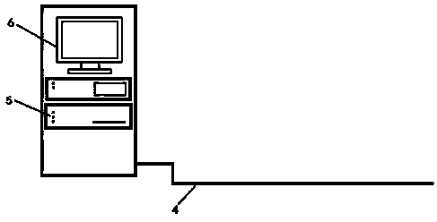
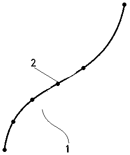
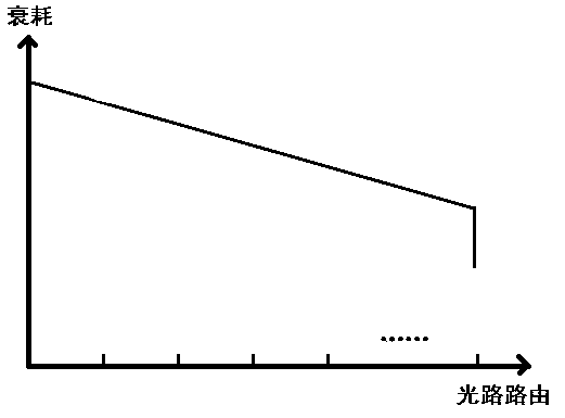

Image

  • Optical fiber fault monitoring and accurate positioning method base on GIS
  • Optical fiber fault monitoring and accurate positioning method base on GIS
  • Optical fiber fault monitoring and accurate positioning method base on GIS

Examples


Embodiment Construction

[0046] The following will clearly and completely describe the technical solutions in the embodiments of the present invention with reference to the accompanying drawings in the embodiments of the present invention. Obviously, the described embodiments are only some, not all, embodiments of the present invention. Based on the embodiments of the present invention, all other embodiments obtained by persons of ordinary skill in the art without making creative efforts belong to the protection scope of the present invention.

[0047] In describing the present invention, it should be understood that the terms "longitudinal", "transverse", "upper", "lower", "front", "rear", "left", "right", "vertical", The orientation or positional relationship indicated by "horizontal", "top", "bottom", "inner", "outer", etc. are based on the orientation or positional relationship shown in the drawings, and are only for the convenience of describing the present invention and simplifying the descriptio...


PUM


Abstract

The invention discloses an optical fiber fault monitoring and accurate positioning method based on a GIS. The method comprises the steps of determining multiple calibration points on an optical fiberroute under the normal state of an optical fiber; measuring optical path distances of a light ray from the start of the optical fiber to all calibration points, thus forming a distance set; acquiringgeographical coordinates of all the calibration points to form a coordinate set, and forming complete optical fiber route geographical position information; when the optical fiber is faulted, measuring a fault distance of the light ray from the start of the optical fiber to the fault point; finding the optical path distance having the minimum difference with the fault distance in the distance set,and determining a first calibration point closest to the fault point according to the optical path distance with the minimum difference; and acquiring the geographical coordinate of the first calibration point from the coordinate set, wherein the geographical coordinate of the first calibration point can approximately serve as the geographical coordinate of the fault point, and the denser the calibration points are, the higher the accuracy is. The method provided by the invention has the beneficial effect that the fault point of the optical fiber is accurately positioned.

Description

technical field [0001] The invention belongs to the field of communication transmission, and in particular relates to a GIS-based optical cable fault monitoring and precise positioning method. Background technique [0002] As the media in the communication network transmission, optical fiber and optical cable have become the most important link in the network communication link. Due to the particularity of optical fiber fragility and the way optical cables are overhead, buried underground, and laid in underground pipelines, optical cables are extremely vulnerable to damage from external construction and operations, resulting in failures and paralysis of communication networks. [0003] Traditional optical cable faults use OTDTR optical time domain reflectometer to transmit optical pulses to the optical fiber under test. When the optical pulse is transmitted in the optical fiber, due to the nature of the optical fiber itself, it occurs when encountering an attenuation point, ...

Claims


Application Information

Patent Timeline
IPC IPC(8): H04B10/07H04B10/077H04B10/079
CPCH04B10/07H04B10/0771H04B10/0791
Inventor 袁周雷菅云峰周军张静黎载红
Owner PINGHU BOHUI COMM TECH
Learn More