


Quick Research
Generate reliable direction feasibility study reports for your R&D in just a few steps.

Technical Q&A
Discover and master advanced knowledge NOW. Basics, ideas, possibilities, all at once.

Find Solutions
As an expert in R&D theories, this can generate solutions to your technical problems instantly.

Evaluate Feasibility
Analyze your overall solution with one click, know your potential R&D risks in advance.

Monitor Landscape
Get weekly tech updates, stay abreast of the latest tech innovations and key insights.
Humidifier and air conditioner
A technology for humidifiers and air conditioners, which is applied in air conditioning systems, air humidification systems, heating methods, etc. It can solve the problems of harmful microorganisms in humidifiers, unfavorable humidifier sanitation, and dirt deposition in humidifiers. The problem of ash entering the fog hole, ensuring long-term health and hygiene use, and good humidification effect
- Summary
- Abstract
- Description
- Claims
- Application Information
AI Technical Summary
Problems solved by technology
Method used
Image

Examples
Embodiment 1
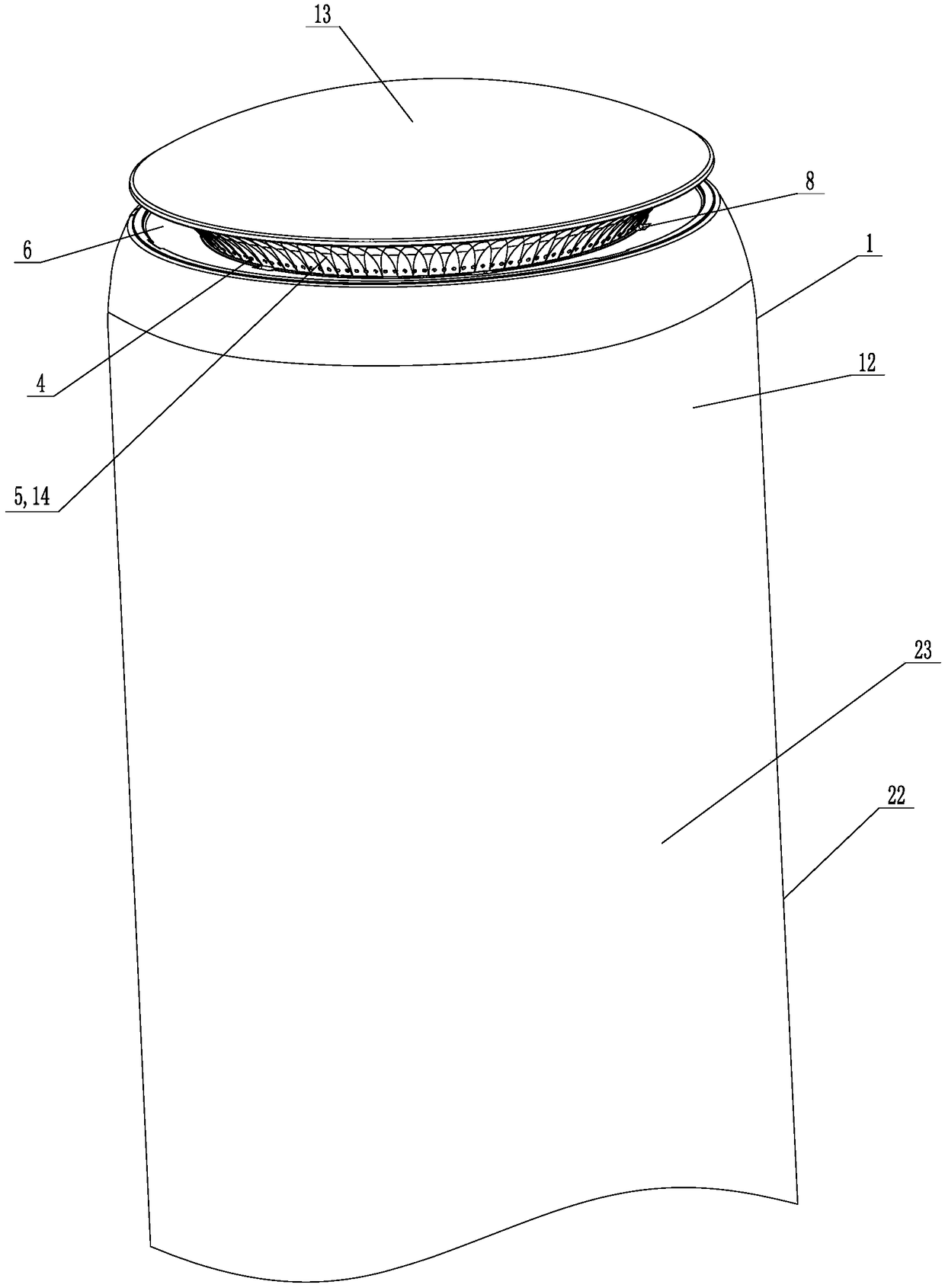
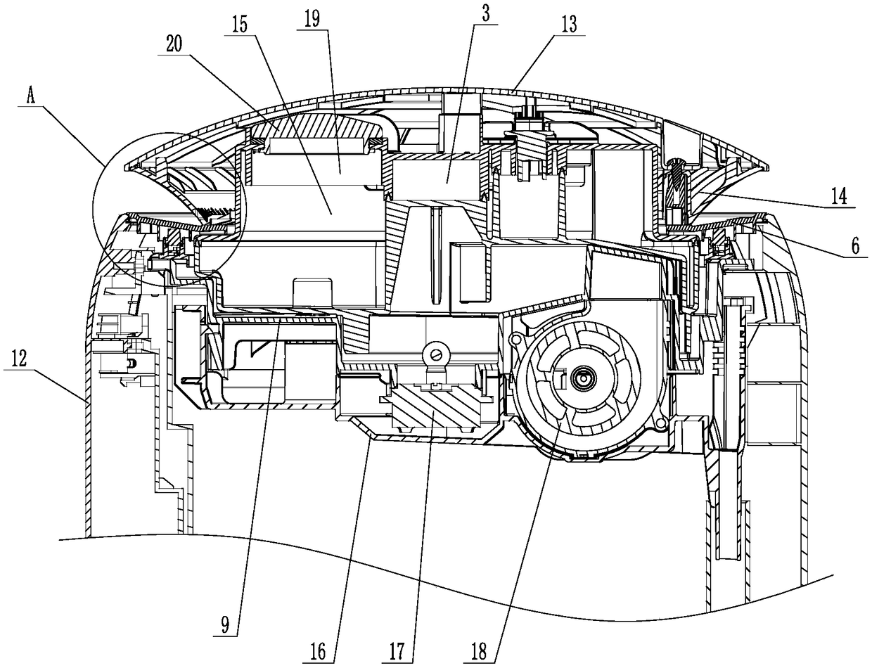
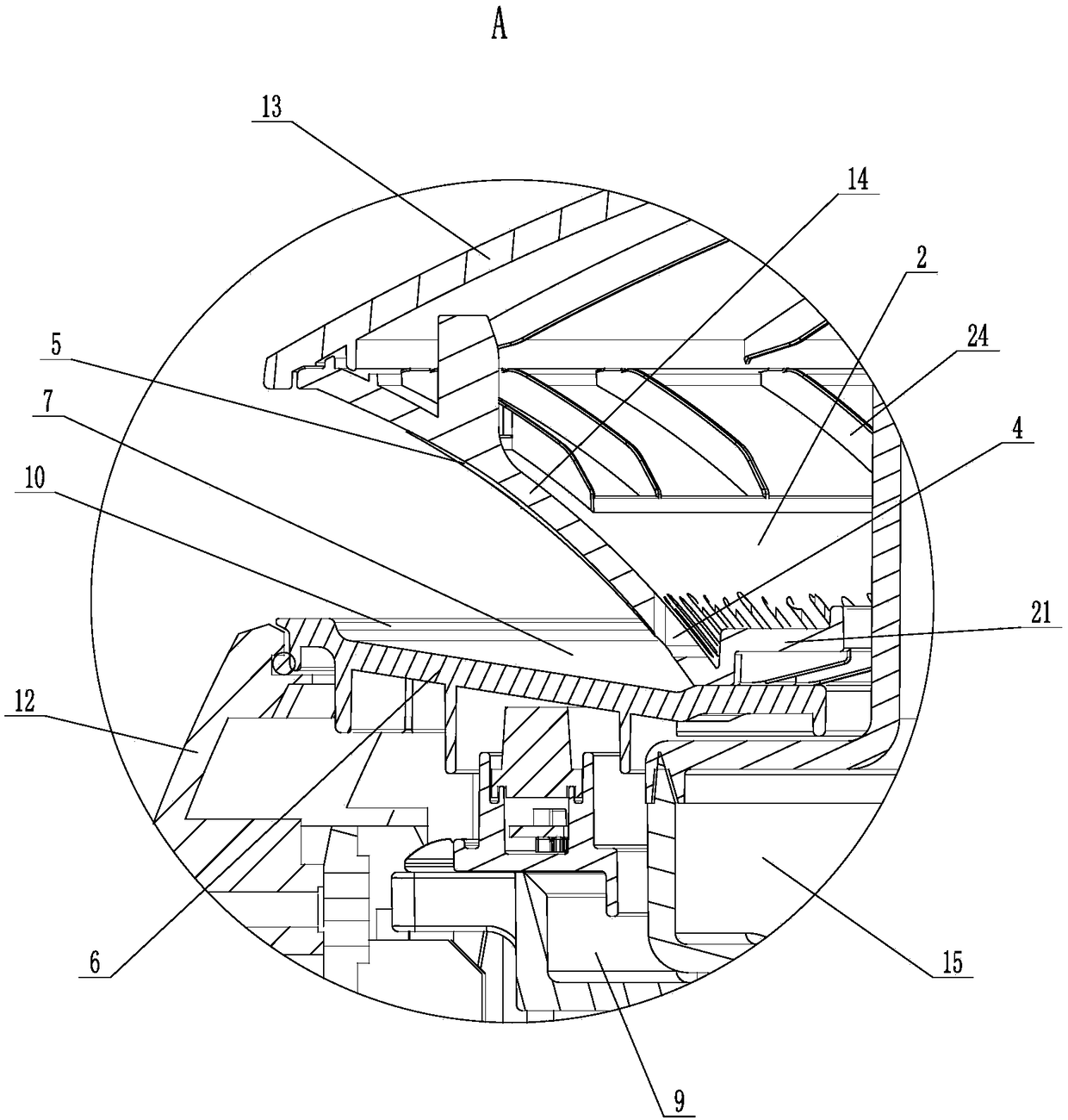
[0046] Such as Figure 1 to Figure 7 As shown, the humidifier of the present invention includes a body 1, and the upper end of the body 1 is provided with a cavity 2, a mist inlet hole 3 and at least one mist outlet hole 4, and both the mist inlet hole 3 and the mist outlet hole 4 communicate with the cavity 2, The mist outlet hole 4 is arranged on the side wall of the cavity 2, and the upper guide surface 5 is provided on the outer surface of the side wall of the cavity 2 above the mist outlet hole 4 and gradually slopes outward from bottom to top.
[0047] The outer surfaces of the side walls of the cavity 2 are upper guide surfaces 5 , and the outlet of the mist outlet hole 4 is located on the upper guide surface 5 and is close to the lower end of the upper guide surface 5 .
[0048] The main body 1 is also provided with a mist guide plate 6, which is located at the lower end of the side wall of the cavity 2, and the upper surface of the mist guide plate 6 is provided with ...
Embodiment 2
[0065] Such as Figure 1 to Figure 8 As shown, the air conditioner of the present invention includes a floor-standing indoor unit 22 and the humidifier in Embodiment 1. The humidifier is arranged on the top of the floor-standing indoor unit 22. In this embodiment, the floor-standing indoor unit 22 includes a housing 23 for humidifying The casing 3 of the humidifier is located above the casing 23, and the casing 3 of the humidifier is integrated with the casing 23.
[0066] The side wall of the cavity 2 is divided into two parts: a section with holes 24 and a section without holes 25. The mist outlet hole 4 is arranged on the section with holes 24. In this embodiment, the section with holes 24 and the section without holes 25 are both arranged on the On the side cover 14.
[0067] The circumferential length of the non-porous section 25 accounts for 1 / 4 to 3 / 4 of the circumferential length of the side wall of the entire cavity 2 (i.e. the side wall of the side cover 14), prefer...
PUM
 Abstract
Description
Claims
Application Information
 - R&D Engineer
- R&D Manager
- IP Professional
- Industry Leading Data Capabilities
- Powerful AI technology
- Patent DNA Extraction
Browse by: Latest US Patents, China's latest patents, Technical Efficacy Thesaurus, Application Domain, Technology Topic, Popular Technical Reports.
© 2024 PatSnap. All rights reserved.Legal|Privacy policy|Modern Slavery Act Transparency Statement|Sitemap|About US| Contact US: help@patsnap.com