
Low separation load joint with flexible self-compensation

A self-compensating and flexible technology, applied in space navigation equipment, space navigation equipment, space navigation aircraft, etc., can solve problems such as small fit gap between plug and socket, difficult inspection of excess, and risk of excess, to achieve separation The effect of high reliability, elimination of excess inconvenient removal problems, and elimination of risk of extrusion

Active Publication Date: 2018-11-27
BEIJING INST OF SPACE LAUNCH TECH +1
View PDF5 Cites 1 Cited by
  • Summary
  • Abstract
  • Description
  • Claims
  • Application Information

AI Technical Summary

Problems solved by technology

[0004] This kind of connection joint still has certain shortcomings in actual use. The joint is radially inserted and sealed, and the fit gap between the plug and the socket is very small. Due to the long separation stroke when pulling out, there is a risk of sticking under extreme working conditions. ; There are multiple elongated holes inside the connecting joint, which are in the axial direction of the joint, and there are problems such as difficult processing and difficult inspection and cleaning of redundant objects; when the O-ring at the front of the plug is inserted into the joint body, it needs to cross the central annular groove, and the processing And when the operation is improper, there is a risk of cutting the sealing ring and generating excess

Method used


Image

  • Low separation load joint with flexible self-compensation
  • Low separation load joint with flexible self-compensation
  • Low separation load joint with flexible self-compensation

Examples


Embodiment Construction

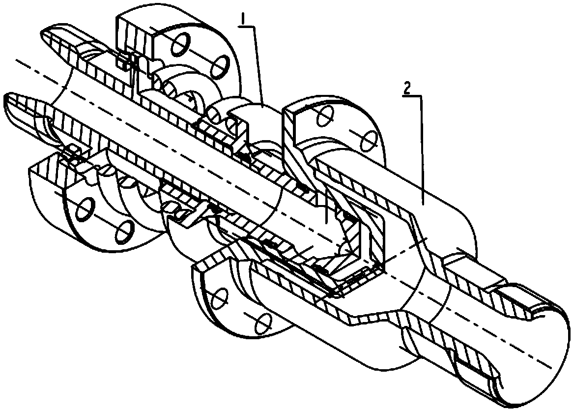
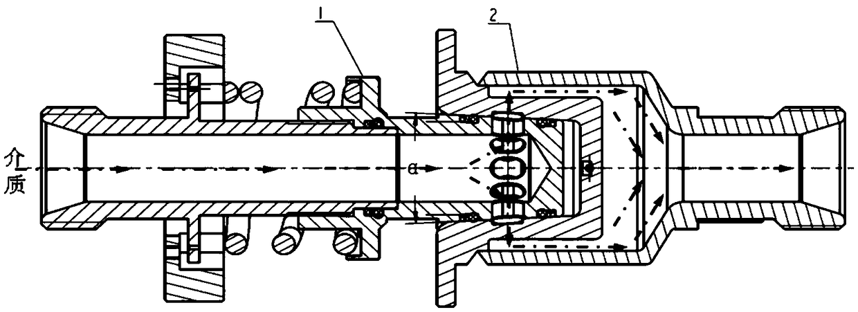
[0043] Such as figure 1 As shown, a low separation load joint with flexible self-compensation of the present invention includes a plug 1 and a socket 2, the front end of the plug 1 is connected to the rear end of the socket 2, and both the plug 1 and the socket 2 are rotary bodies. The plug 1 is installed on the ground equipment through the guide seat 13, and the rear end is connected with the ground air supply / liquid supply equipment, such as image 3 As shown, the plug 1 includes a plug body 11, a fixing seat 14, a guide seat 13 and a spring 12. The plug body 11 has a hollow inner cavity structure, and the inner cavity of the plug body 11 is a plug body channel. Such as Figure 5 As shown, the front part of the plug body 11 is a conical surface, and two front and rear outer annular sealing grooves are arranged on the conical surface structure. Sealing rings are respectively arranged in the two outer annular sealing grooves, and the outer annular sealing groove near the top of...


PUM


Abstract

The invention discloses a low separation load joint with flexible self-compensation, and relates to a joint of an air supply connector and a liquid supply connector in a carrier rocket (a guided missile) which is more sensitive in rocket-ground separation load requirement, and high in falling separation reliability requirement. The provided joint aims to reduce separation load, has a butting automatic guide positioning function and an automatic flexible compensation function, and is capable of realizing separation without clamping stagnation, and improving butting and separation reliability. The joint comprises cooperatively installed socket and plug. The plug comprises a plug body, a fixing base, a guiding base and a spring. The socket comprises a sealing base and an outer sleeve. The plug body is provided with a hollow cavity structure. The front part of the plug body is a conical surface. The fixing base can be screwed in the plug body and cooperatively installed with the plug body.The guiding base is sheathed at the outer side of the fixing base. The spring is pre-compressed and installed between the plug body and the guiding base. The rear part of the sealing base is providedwith a conical surface structure which has the same inclination angle of the conical surface as the plug body. The rear part of the outer sleeve is sheathed at the outer side of the sealing base.

Description

technical field [0001] The invention relates to a connecting piece, in particular to a joint used for a gas supply connector and a liquid supply connector in a launch vehicle (missile) which is sensitive to the load requirements of the rocket-ground separation and has high requirements on the reliability of the separation. Background technique [0002] Air supply connectors and liquid supply connectors are usually installed in launch vehicles and missiles, but launch vehicles and missiles are sensitive to the load requirements for rocket-ground separation, and require high reliability for separation and separation. When supplying air or liquid, the connecting equipment generates axial separation load due to the separation load such as blind plate force. The higher the medium pressure and the larger the diameter, the greater the axial separation load. There are high requirements on the rigidity and strength of the connected parts, which will increase the size, volume, weight ...

Claims


Application Information

Patent Timeline
IPC IPC(8): B64G1/00
CPCB64G1/002
Inventor 张振华王爱伟唐强黄福友刘忠明王南甄恩发戴维奇
Owner BEIJING INST OF SPACE LAUNCH TECH
Learn More