Multifunctional suspension equipment for mechanical engineering
A kind of suspension equipment and mechanical engineering technology, which is applied in the direction of manipulators, manufacturing tools, chucks, etc., can solve the problems of different directions of pulling and lifting, different shapes of materials, and the inability of the manipulator to complete the snatch action, so as to achieve strong suspension and lifting capabilities , easy to grab, simple structure effect
- Summary
- Abstract
- Description
- Claims
- Application Information
AI Technical Summary
Problems solved by technology
Method used
Image
Examples
Embodiment 1
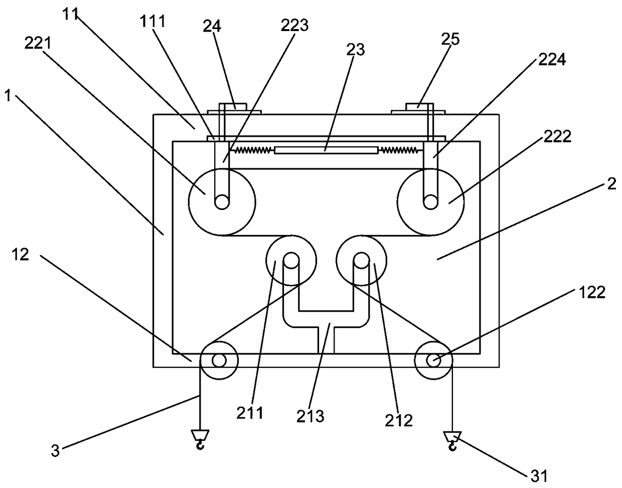
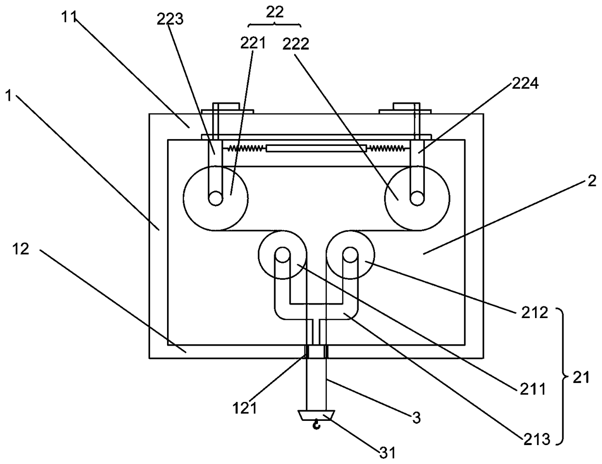
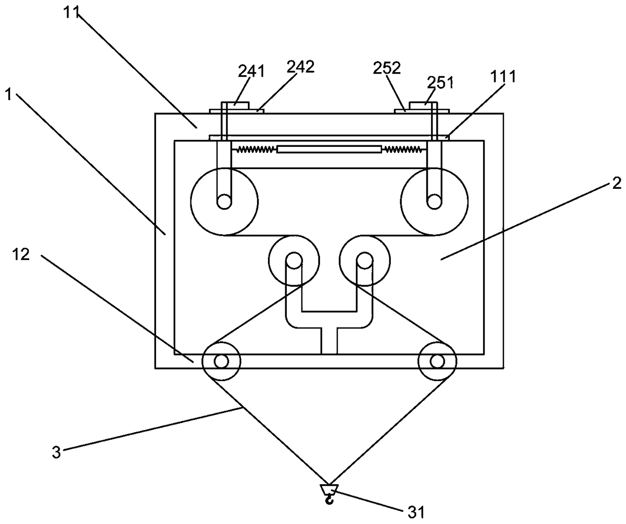
[0027] Embodiment one: if Figures 1 to 4 As shown, it is only one of the embodiments of the present invention, a mechanical engineering multifunctional suspension device, including an engineering frame 1, a functional device 2 arranged in the engineering frame 1, and a functional rope connected to the functional device 2 3. The engineering frame 1 includes an upper frame plate 11 and a lower frame plate 12, the functional device 2 includes a fixed part 21 and a movable part 22, and the fixed part 21 includes a first fixed roller 211, a second fixed roller 212 and For fixing the first fixed roller 211 and the second fixed roller 212 to the fixed frame 213 on the lower frame plate 12, the movable part 22 includes a first movable roller 221 and a second movable roller 222, the first movable roller 221 A movable roller 221 is connected with the upper frame 11 through a first movable rod 223, and the second movable roller 222 is connected with the upper frame 11 through a second m...
Embodiment 2
[0035] Embodiment two, still as Figures 1 to 4 As shown, it is only one of the embodiments of the present invention. In order to make a kind of mechanical engineering multifunctional suspension device of the present invention have better suspension effect and higher safety, the present invention also has the following designs:
[0036] First, the upper frame plate 11 is provided with a chute 111 for facilitating the sliding of the first movable rod 223 and the second movable rod 224 , and the first movable rod 223 and the second movable rod 224 can be carried out on the chute 111 Sliding, the sliding between the first movable rod 223 and the second movable rod 224 is smoother, and the cushioning effect for the load is better.
[0037] Then, the end of the first movable rod 223 is provided with a first induction part 24, and the end 224 of the second movable rod is provided with a second induction part 25, and the first induction part 24 includes a The first movable plate 241...
Embodiment 3
[0040] Embodiment three, such as figure 2 As shown, it is only one of the embodiments of the present invention:
[0041] The lower frame plate 12 is provided with a through hole 121 for facilitating the passing of the functional rope 3, so that while the functional rope 3 plays a role in hanging heavy objects, it also needs to bypass the functional device 2 in the engineering frame 1. , the function rope 3 after winding needs to protrude from the lower end of the engineering frame 1, so the lower frame plate 12 is provided with a through hole 121 to facilitate the function rope 3 to protrude.
[0042] It should be noted that there is at least one through hole 121, and one end of the functional rope 3 protrudes from the through hole 121, or both ends protrude from one through hole 121, or both ends protrude from the same through hole 121 .
PUM
 Abstract
Description
Claims
Application Information
 - R&D Engineer
- R&D Manager
- IP Professional
- Industry Leading Data Capabilities
- Powerful AI technology
- Patent DNA Extraction
Browse by: Latest US Patents, China's latest patents, Technical Efficacy Thesaurus, Application Domain, Technology Topic, Popular Technical Reports.
© 2024 PatSnap. All rights reserved.Legal|Privacy policy|Modern Slavery Act Transparency Statement|Sitemap|About US| Contact US: help@patsnap.com


