
Fault processing system of multi-terminal flexible direct-current transmission line and control method of fault processing system

A DC transmission line, multi-terminal flexible technology, applied in the direction of emergency treatment AC circuit layout, power transmission AC network, etc., can solve the problems of increasing current limiter input, complex structure of current limiter, unfavorable multi-terminal flexible DC system widely used, etc. Achieve the effect of reducing the requirements of breaking capacity and breaking speed, and reducing the rising speed

Pending Publication Date: 2018-11-23
STATE GRID ZHEJIANG ELECTRIC POWER CO LTD HANGZHOU POWER SUPPLY CO
View PDF6 Cites 9 Cited by
  • Summary
  • Abstract
  • Description
  • Claims
  • Application Information

AI Technical Summary

Problems solved by technology

The structure of the current limiter is complex, involving a large number of components, and a bias power supply needs to be configured, which increases the investment of the current limiter, which is not conducive to the wide use in multi-terminal flexible DC systems

Method used


Image

  • Fault processing system of multi-terminal flexible direct-current transmission line and control method of fault processing system
  • Fault processing system of multi-terminal flexible direct-current transmission line and control method of fault processing system
  • Fault processing system of multi-terminal flexible direct-current transmission line and control method of fault processing system

Examples


Embodiment Construction

[0033] The technical solutions of the present invention will be further described below in conjunction with the accompanying drawings, but the present invention is not limited to these embodiments.

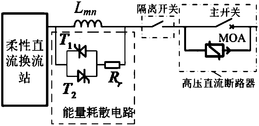
[0034] The basic idea of ​​the present invention is to add a current-limiting inductance and an energy dissipation circuit to the existing multi-terminal flexible direct current transmission line, the current-limiting inductance is used to limit the fault current, and the energy dissipation circuit is used to dissipate the energy of the fault current.

[0035] combined with figure 1 , this embodiment provides a fault handling system for a multi-terminal flexible DC transmission line, including a high-voltage DC circuit breaker connected to each output terminal of the flexible DC converter station, and a high-voltage DC circuit breaker connected to the output terminal of the flexible DC converter station. The current-limiting inductance Lmn and the energy dissipating circuit betwee...


PUM


Abstract

The invention relates to the technical field of flexible direct current output, in particular to a fault processing system of a multi-terminal flexible direct-current transmission line and a control method of the fault processing system. The system comprises a high-voltage direct-current circuit breaker which is connected to the output ends of a flexible direct-current convertor station separately, and further comprises a current-limiting inductor and an energy dissipation circuit, wherein the current-limiting inductor and the energy dissipation circuit are connected between the output end ofthe flexible direct-current converter station and the high-voltage direct-current circuit breaker; the current-limiting inductor is connected with the energy dissipation circuit in parallel, and the current-limiting inductor is used for limiting the fault current; the energy dissipation circuit is used for dissipating energy of the fault current. By means of the method and the device, the effect that the current limiting inductor can better inhibit the peak of the fault current can be achieved, and the rising speed of the fault current is reduced, and the requirements of fault removal on the on-off capacity and the on-off speed of the high-voltage direct-current circuit breaker can be reduced; and an energy absorption resistor and a metal oxide lightning arrester MOA in the high-voltage direct-current circuit breaker jointly dissipate the energy of the fault current, so that the fault current can be accelerated to be extinguished, thereby improving the fault isolation speed.

Description

technical field [0001] The invention relates to the technical field of flexible DC output, in particular to a fault handling system and a control method for a multi-terminal flexible DC transmission line. Background technique [0002] The multi-terminal flexible DC transmission system can independently adjust active and reactive power, and has broad application prospects in new energy and other fields. However, due to the low impedance characteristic of the DC side of the multi-terminal flexible DC transmission system, the peak value of the fault current of the DC line is large and the rising speed is fast. Compared with the traditional high-voltage direct current transmission system based on grid commutation converters, the multi-terminal flexible direct current transmission system lacks the low-voltage current limiting function, and the extremely large fault current is likely to damage the converter equipment and line insulation. At the same time, the breaking capacity an...

Claims


Application Information

Patent Timeline
IPC IPC(8): H02J3/36
CPCH02J3/36H02J3/001Y02E60/60
Inventor 刘剑何雨微朱明陈煜沈毅君周百龄孙超方一楠杨翾方响王立钱晓伟陈敏孙霏张智光潘敏奇童洁
Owner STATE GRID ZHEJIANG ELECTRIC POWER CO LTD HANGZHOU POWER SUPPLY CO
Learn More