Magnetic field direction measuring method

A measurement method and azimuth technology, which is applied to measurement devices, surveying and navigation, compass and other directions, can solve the problems of skeleton and coil processing, winding process deviation, difficult to correlate, difficult to ensure the magnetic field vector direction test, etc., to achieve accuracy high effect

Active Publication Date: 2018-11-23
HARBIN INST OF TECH
View PDF20 Cites 4 Cited by
  • Summary
  • Abstract
  • Description
  • Claims
  • Application Information

AI Technical Summary

Problems solved by technology

[0002] At present, the precision of the vector magnetic field is an effective means and way for human beings to explore the world. Among them, the magnetic field modulus test tools are abundant and have high precision. Typical magnetometers include: fluxgate sensors, atomic magnetometers, proton magnetometers, superconducting Quantum interferometer, etc., the highest accuracy can reach Pete level; but the magnetic field vector direction test is difficult to ensure. The magnetic source coil is made of a skeleton as a constraint and is wound by a multi-strand coil. The processing and winding process of the skeleton and coil will introduce deviations. Therefore, the geometric axis of the coil will deviate from the axis of the magnetic field generated by the coil. This deviation There is no accurate way to measure
[0003] It is impossible to calibrate the magnetic axis direction of the standard magnetic source coil, and it is also impossible to calibrate the spatial coordinate axis relationship between the vector magnetic sensor and other types of sensors; a t

Method used


Image

  • Magnetic field direction measuring method
  • Magnetic field direction measuring method
  • Magnetic field direction measuring method

Examples


Embodiment Construction

[0016] The present invention will be described in further detail below in conjunction with the accompanying drawings: the present embodiment is implemented on the premise of the technical solution of the present invention, and detailed implementation is provided, but the protection scope of the present invention is not limited to the following embodiments.

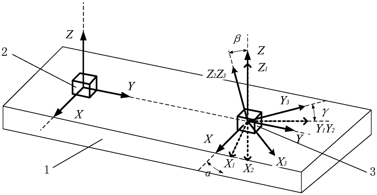
[0017] Such as figure 1 Shown, a kind of magnetic field azimuth measurement method involved in this embodiment, its steps are as follows,

[0018] One, establish the standard device of magnetic measuring axis coordinate system and celestial body coordinate system, comprise vector magnetic sensor, other kind of sensor of correlation celestial body coordinate system in the device, described vector magnetic sensor and other kind of sensor are installed on the rigidity platform, The rigid platform is made of non-remanent magnetism and non-magnetic materials.

[0019] 2. The combination of the vector magnetic sensor and other ...


PUM


Abstract

The invention provides a magnetic field direction measuring method which is used for calibrating an included angle relationship between a measured magnetic field direction and an earth coordinate system, and can realize calibration of an euler angle between a magnetic sensor and other sensors, a standard magnetic source magnetic field direction and the like. A set of standard positions of a magnetic measuring axis coordinate system and an earth coordinate system (or a celestial body coordinate system) is established, and a physical quantity tester for a vector magnetic sensor and an associatedearth coordinate system (or the celestial body coordinate system) is used for measuring associated physical quantity to construct a relationship with the earth coordinate system (or the celestial body coordinate system), and an included angle relationship between a measuring axis of the magnetic sensor and a measuring axis of a gyro theodolite or a star sensor and the like is measured by virtue of the relationship between earth magnetic fields and the earth coordinate system (or the celestial body coordinate system), so that the relationship between the coordinate system of the magnetic sensor and a coordinate axis euler angle of apparatuses such as the gyro theodolite or the star sensor is calibrated, and a relative relationship between a standard magnetic source coil magnetic axis and the earth coordinate system (or the celestial body coordinate system) is measured.

Description

technical field [0001] The invention relates to the field of magnetic field measurement, which is used for calibrating the angle relationship between the measurable magnetic field direction and the earth coordinate system, and in particular is a magnetic field orientation measurement method. Background technique [0002] At present, the precision of the vector magnetic field is an effective means and way for human beings to explore the world. Among them, the magnetic field modulus test tools are abundant and have high precision. Typical magnetometers include: fluxgate sensors, atomic magnetometers, proton magnetometers, superconducting Quantum interferometer, etc., the highest accuracy can reach Pete level; but the magnetic field vector direction test is difficult to ensure. The magnetic source coil is made of a skeleton as a constraint and is wound by a multi-strand coil. The processing and winding process of the skeleton and coil will introduce deviations. Therefore, the g...

Claims


Application Information

Patent Timeline
IPC IPC(8): G01C17/00
CPCG01C17/00
Inventor 潘东华林生鑫李立毅李吉刘添豪金银锡
Owner HARBIN INST OF TECH
Why Eureka
Try Eureka