
Manual material dispersing valve

A material distributing valve and handle technology, which is applied in the direction of transportation, packaging, slideway, etc., can solve the problems of inability to accurately control the opening and closing of the valve body, the high cost of using the electric flap valve, and the easy material binding of the flapper valve, etc., to achieve convenience Diversion, simple structure, low cost of use

Pending Publication Date: 2018-11-23
HEBEI IRON AND STEEL
View PDF14 Cites 2 Cited by
  • Summary
  • Abstract
  • Description
  • Claims
  • Application Information

AI Technical Summary

Problems solved by technology

[0003] The purpose of the present invention is to provide a manual material distributing valve to solve the problems existing in the prior art that the flapper valve is easy to accumulate material and affect the normal opening and closing, and the use cost of the electric flap valve is high, and the degree of opening and closing of the valve body cannot be accurately controlled. technical issues

Method used


Image

  • Manual material dispersing valve
  • Manual material dispersing valve
  • Manual material dispersing valve

Examples


Embodiment Construction

[0027] In order to make the technical problems, technical solutions and beneficial effects to be solved by the present invention clearer, the present invention will be further described in detail below in conjunction with the accompanying drawings and embodiments. It should be understood that the specific embodiments described here are only used to explain the present invention, not to limit the present invention.

[0028] It should be noted that when an element is referred to as being “fixed” or “disposed on” another element, it may be directly on the other element or be indirectly on the other element. When an element is referred to as being "connected to" another element, it can be directly connected to the other element or indirectly connected to the other element.

[0029] It is to be understood that the terms "length", "width", "top", "bottom", "front", "rear", "left", "right", "vertical", "horizontal", "top" , "bottom", "inner", "outer" and other indicated orientations...


PUM


Abstract

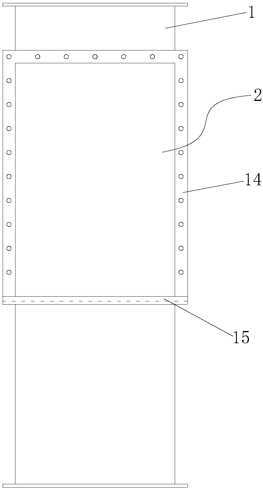
The invention provides a manual material dispersing valve, and belongs to the field of material dispersing equipment. The manual material dispersing valve comprises a main chute, a material dispersingopening, a material dispersing chute, a rotary shaft, a turning plate, a handle, an inserting pin and an inserting hole structure, wherein the material dispersing opening is formed in the material dispersing side wall of the main chute and communicated with the material dispersing chute, the central axis of the rotary shaft is parallel to the material dispersing side wall, the rotary shaft is located on the lower side of the material dispersing opening, the turning plate is rotatably connected with the material dispersing side wall through the rotary shaft, the handle is fixedly connected toone end of the rotary shaft, the inserting pin is clamped on the handle, and the inserting hole structure is arranged in the main chute or / and the material dispersing chute, used for being in inserting fit with the inserting pin and provided with multiple inserting holes. The length of the turning plate in the direction perpendicular to the direction of the rotary shaft is larger than the width ofthe inner cavity of the main chute in the direction perpendicular to the direction of the rotary shaft. The manual material dispersing valve avoids that since material caking occurs on the turning plate, rotating of the turning plate and opening and closing of the main chute and the material dispersing chute are affected; positioning is flexible and accurate, the on-off degree of a valve body canbe accurately controlled, materials can be accurately, conveniently and efficiently distributed, and the manual material dispersing valve is simple in structure, low in using cost and further capableof being used for rapid dispersion of materials in process accidents.

Description

technical field [0001] The invention belongs to the technical field of material distribution equipment, and more specifically relates to a manual material distribution valve. Background technique [0002] In industrial production, it often involves the diversion of solid bulk materials in the process chute or the dispersion of materials during process accidents. In the existing process, there is a material distribution structure that uses the lower end of the three-way chute to install manual or electric gate valves. However, due to the gate valve The structure of the main body is defective. After a period of use, materials will be stuck or stuck in the slot of the flapper valve, which will cause the manual or electric flapper valve to fail to switch normally. At the same time, when the distribution chute is not used for a long time, the The material plate is formed into a whole piece, and when it is used again, it is necessary to disassemble the gate valve to deal with the ...

Claims


Application Information

Patent Timeline
Patent Type & Authority Applications(China)
IPC IPC(8): B65G11/20
CPCB65G11/206
Inventor 冯国晟靳倩倩张润洪王震宇袁国静宋波
Owner HEBEI IRON AND STEEL
Learn More