
Flapping wing type energy obtaining device for controlling lift augmentation by adopting circular rector

A circulation control and energy harvesting technology, which is applied in aircraft control, helicopters, transportation and packaging, etc., can solve the problems of high manufacturing cost of flapping wing energy harvesting devices, cannot be used as a unified whole, and complex structure, so as to improve energy harvesting. Effects of efficiency, lift increase, and circulation increase

Inactive Publication Date: 2018-11-23
UNIV OF SHANGHAI FOR SCI & TECH
View PDF8 Cites 6 Cited by
  • Summary
  • Abstract
  • Description
  • Claims
  • Application Information

AI Technical Summary

Problems solved by technology

In the present invention, flaps are applied to the flapping wing energy harvesting device, which increases the camber of the airfoil, improves the lift coefficient of the airfoil, thereby improves the energy harvesting efficiency, but the energy collection components, flapping wings, main shaft, movable flaps, etc. They are all separate parts, which are connected to form a whole, and cannot be used as a unified whole. The structure is relatively complicated, and the manufacturing cost of the flapping wing energy-capturing device is relatively high.

Method used


Image

  • Flapping wing type energy obtaining device for controlling lift augmentation by adopting circular rector
  • Flapping wing type energy obtaining device for controlling lift augmentation by adopting circular rector
  • Flapping wing type energy obtaining device for controlling lift augmentation by adopting circular rector

Examples


Embodiment Construction

[0017] The idea, specific structure and technical effects of the present invention will be further described below in conjunction with the accompanying drawings, so as to fully understand the purpose, features and effects of the present invention.

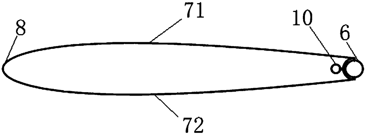
[0018] refer to figure 1 , the flapping wing type energy-gathering device that adopts circulation control to increase the lift of the present invention, the flapping wing has an upper airfoil 71, a lower airfoil 72, a leading edge 8 and a trailing edge 6, and the trailing edge 6 is semicircular arc-shaped, and the inside of the flapping wing A jet device 10 is provided, and a high-pressure jet can be formed inside the jet device 10 .

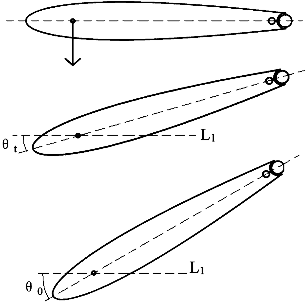
[0019] refer to figure 2 , upper airfoil 71 offers upper nozzle 51 near trailing edge 6 places, lower airfoil 72 offers lower nozzle 52 near trailing edge 6 places, upper nozzle 51 and lower nozzle 52 are symmetrical, and link to each other with jet flow device 10. The jet device 10 includes a pne...


PUM


Abstract

The invention relates to a flapping wing type energy obtaining device for controlling lift augmentation by adopting circular rector. A flapping wing is provided with an upper wing surface, a lower wing surface, a front edge and a tail edge, wherein the tail edge has a semi-circular arc shape, a position, which is close to the tail edge, of the upper wing surface is provided with an upper nozzle, aposition, which is close to the tail edge, of the lower wing surface is provided with a lower nozzle, the upper nozzle is symmetric with the lower nozzle, the upper nozzle and the lower nozzle are connected with a jet flow device arranged inside the flapping wing, the jet flow device comprises a pneumatic pump, a pipeline, an alternate valve and a flow jet channel which are successively connected, the flow jet channel comprises an upper channel and a lower channel, which are symmetric and are respectively communicated with the upper nozzle and the lower nozzle; when the flapping wing does lifting movement downwards from the highest position or does lifting movement upwards from the lowest position, the jet flow is sprayed out from the lower nozzle through the lower channel or sprayed outfrom the upper nozzle through the upper channel with the control of the alternate valve. After mixing with outer airflow, the jet flow forms a wall attachment effect along a bent semi-circular tail edge surface, the circular rector can be increased, and the lift force of the flapping wing is remarkably increased, so that the energy obtaining efficiency is improved.

Description

technical field [0001] The invention relates to a flapping wing energy harvesting device, in particular to a flapping wing energy harvesting device adopting circulation control to increase lift. Background technique [0002] The flapping wing is an important structure of a new type of aircraft designed and manufactured based on the principle of bionics to imitate the flight of birds and insects. Compared with fixed-wing and rotary-wing flight, this type of aircraft has the following unique advantages: it can take off in situ or in a small field, excellent flight maneuverability and hovering performance in the air, and low flying cost. It will lift, hover And the propulsion function is integrated in the flapping wing system, which can carry out long-distance flight with very little energy, so it is more suitable for performing tasks under long-term non-energy replenishment and long-distance conditions. [0003] Flying creatures in nature adopt flapping wing flight without ex...

Claims


Application Information

Patent Timeline
IPC IPC(8): B64C33/02B64C21/04
CPCB64C21/04B64C33/02
Inventor 孙晓晶苏子昂
Owner UNIV OF SHANGHAI FOR SCI & TECH
Learn More