
Parallel Centrifugal Fan

A centrifugal fan and machine base technology, which is applied in the direction of mechanical equipment, machine/engine, liquid fuel engine, etc., can solve the problems of ordinary centrifugal fan axial length limit, low efficiency, large pressure loss, etc.

Active Publication Date: 2020-01-21
WENDENG HAODUN FAN
View PDF9 Cites 0 Cited by
  • Summary
  • Abstract
  • Description
  • Claims
  • Application Information

AI Technical Summary

Problems solved by technology

[0006] The purpose of the present invention is to overcome the disadvantages of large pressure loss and low efficiency of ordinary cross-flow fans, and overcome the disadvantages of limited axial length of ordinary centrifugal fans, and provide a fan with unlimited axial length and high output air pressure. , Parallel centrifugal fans with high efficiency

Method used


Image

  • Parallel Centrifugal Fan
  • Parallel Centrifugal Fan
  • Parallel Centrifugal Fan

Examples


Embodiment Construction

[0040] The present invention is further described below in conjunction with accompanying drawing.

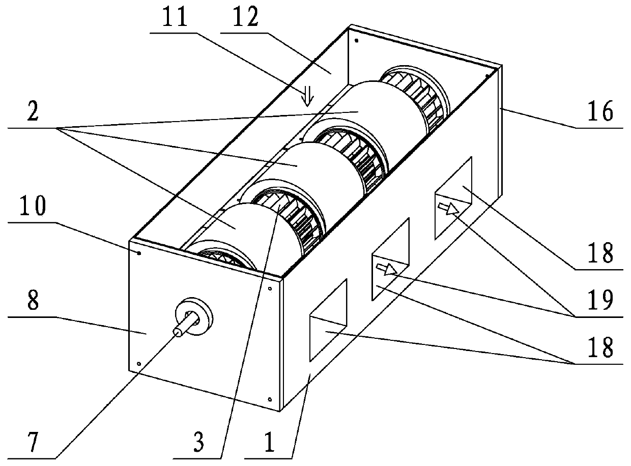
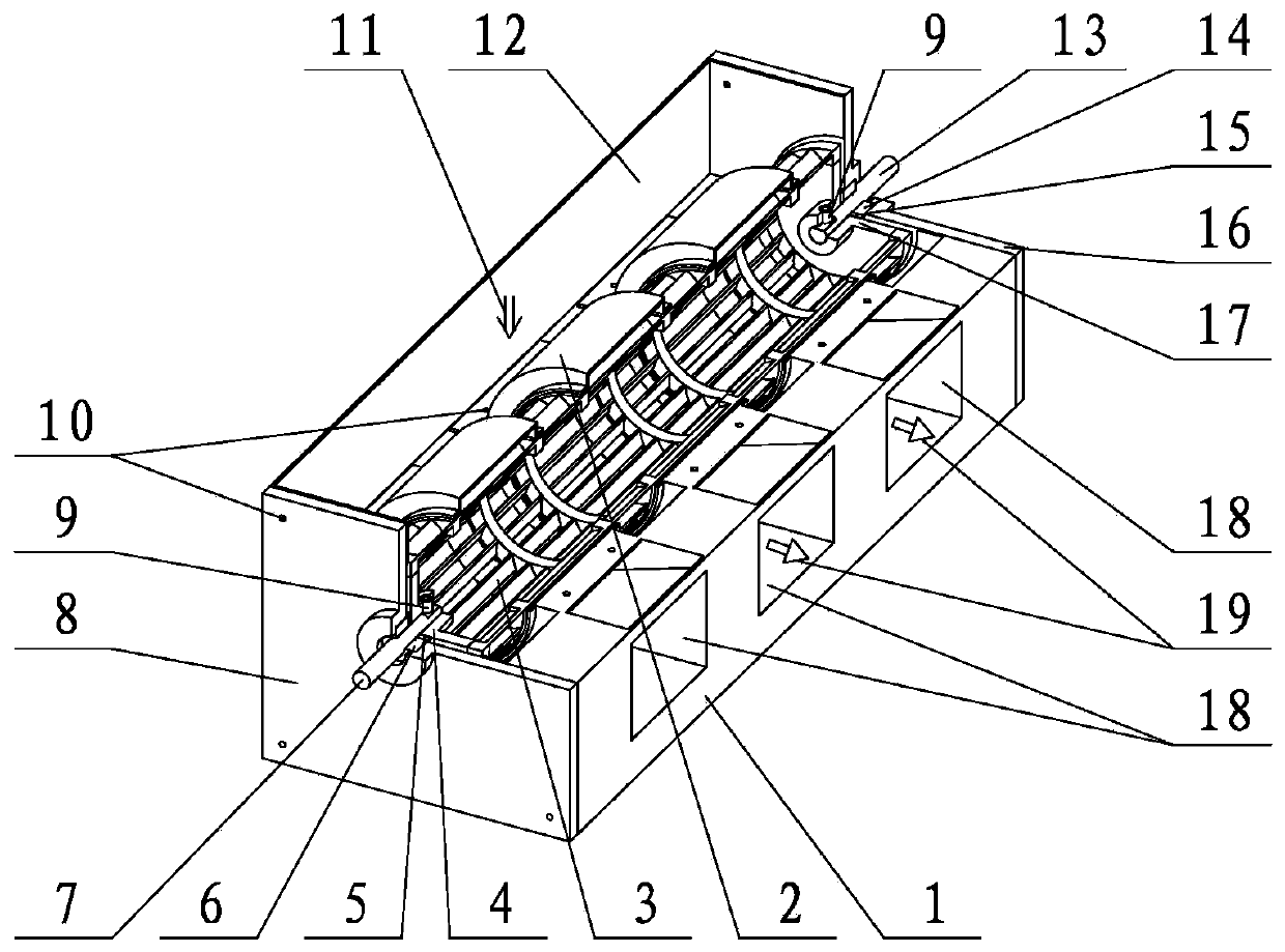
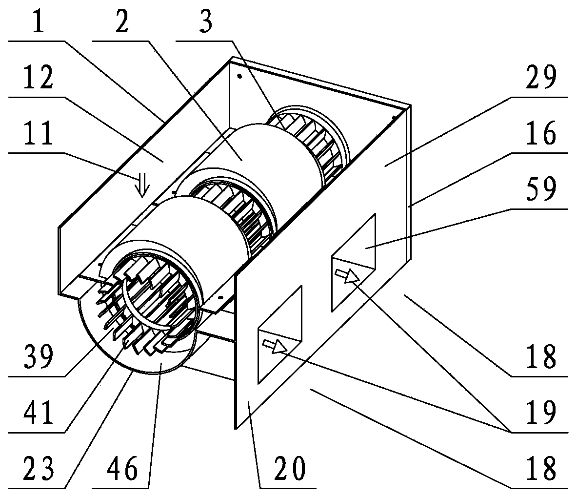
[0041] refer to figure 1 , figure 2 , Figure 18 , Figure 19 , The centrifugal fan includes a base part and an impeller part. The impeller part is installed in the inner cavity of the machine base part, and the motor is installed at one axial end of the machine base part. The base 1 of the base component is axially distributed with several confluence volute plates 23 and several centrifugal volute plates 57, and the confluence volute plates 23 and centrifugal volute plates 57 are arranged at intervals along the axial direction. A centrifugal volute inner cavity 59 is formed between the centrifugal guide volute 2 of several machine base components and the centrifugal volute plate 1 57 of the machine base 1, and the confluence volute plate 23 of the machine base 1 radially inwardly forms the inner cavity of the confluence volute. Cavity 46. The confluence volute inner cavi...


PUM


Abstract

The invention discloses a parallel centrifugal fan and relates to a fan. The parallel centrifugal fan comprises a fan seat part and an impeller part. When the centrifugal fan operates, in the processthat a motor drives an impeller of the impeller part to rotate, part of airflow in an air inlet inner cavity is stirred by the impeller to flow to a confluence volute inner cavity, the flow of the airflow entering an impeller inner cavity is increased, the large-flow airflow is decelerated and pressurized in a centrifugal volute inner cavity, and thus the pressure of the airflow overall output bythe centrifugal fan is increased. In the process that the airflow enters the impeller inner cavity from the confluence volute inner cavity, impeller blades apply the action of force to the airflow, sothat the airflow flows from an impeller confluence section to an impeller centrifugal section in a low-energy-loss mode. Through the structural characteristics of the confluence volute inner cavity,the sectional area of the airflow entering the impeller inner cavity is increased, the axial length of the impeller confluence section is decreased, and thus the centrifugal fan is compact in structure. The centrifugal fan has the advantages that the axial length is not limited, the pressure of the output airflow is large, and the efficiency is high.

Description

technical field [0001] The invention relates to a parallel centrifugal fan, which relates to a fan, in particular to a parallel centrifugal fan with unlimited axial length. Background technique [0002] The types of fans commonly used in home appliances include axial fans, cross-flow fans, and centrifugal fans. Its typical application product examples are vertical fans using axial fans, range hoods using centrifugal fans, and indoor units of air conditioners using cross-flow fans. Axial flow fans are characterized by large flow, low pressure, and high noise. The structure of the axial flow fan is simple. [0003] The cross-flow fan is characterized by moderate flow, moderate pressure and low noise. The axial length of the cross-flow fan is not limited, and the airflow at the air outlet is evenly distributed along the axial direction of the cross-flow fan. Compared with the axial flow fan, the airflow of the cross-flow fan flows through the impeller, and the airflow is af...

Claims


Application Information

Patent Timeline
Patent Type & Authority Patents(China)
IPC IPC(8): F04D25/08F04D25/16F04D29/00F04D29/28F04D29/42F04D29/62
CPCF04D25/08F04D25/163F04D25/166F04D29/002F04D29/283F04D29/4226F04D29/626
Inventor 赵晓东
Owner WENDENG HAODUN FAN
Learn More