
Foldable retractable structure and retractable method for undercarriage

A landing gear and foldable technology, applied in the field of aircraft landing gear, can solve the problems of increasing the storage space of the landing gear bay 14, limited installation and arrangement of the landing gear, and small pressure angle of the retractable actuator, so as to improve the reliability of the landing gear. performance, compact structure, optimized weight and space

Active Publication Date: 2020-04-10
LANDING GEAR ADVANCED MFG
View PDF4 Cites 0 Cited by
  • Summary
  • Abstract
  • Description
  • Claims
  • Application Information

AI Technical Summary

Problems solved by technology

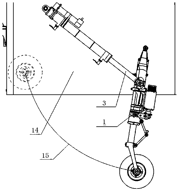
This type of retractable landing gear has a simple structure, and the retractable actuating cylinder directly drives the undercarriage to rotate and retract. Usually, the stroke of the retractable actuating cylinder with this structure is longer, resulting in a larger space arrangement for the retracting actuating cylinder. Thereby the storage space of the landing gear compartment 14 is increased; the retractable actuating cylinder of this retractable mode is arranged on the same side of the landing gear retractable movement, and for the front landing gear retractable toward the nose, due to the limited space , often brings limitations to the installation and arrangement of the landing gear; at the same time, this structure has a small pressure angle of the retractable actuator near the retracted position, resulting in low work efficiency

Method used


Image

  • Foldable retractable structure and retractable method for undercarriage
  • Foldable retractable structure and retractable method for undercarriage
  • Foldable retractable structure and retractable method for undercarriage

Examples


Embodiment Construction

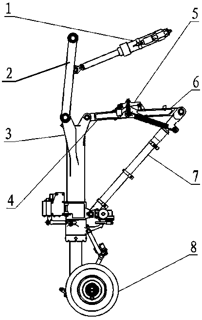
[0031] Such as figure 2 As shown, an embodiment of the landing gear folding retractable structure of the present invention includes a swing guide mechanism and a planar link mechanism, wherein the retractable actuator 1 and the support arm 2 form a swing guide mechanism, and the swing guide mechanism relies on the retractable The telescopic movement of the actuator 1 provides a power source for retracting and retracting the landing gear; the landing gear strut 3, the upper block lock strut 4, the lower block lock strut 6 and the strut 7 are sequentially hinged together to form a planar linkage, The planar link mechanism realizes the folding and retracting of the landing gear under the swing driving of the support arm 2, thereby reducing the retractable and storage space of the landing gear.

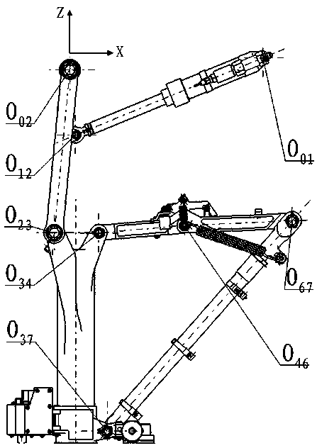
[0032] As shown in Figure 3 a- Figure 3c As shown, one end of the retractable actuator 1 is connected to the body on the first hinge axis O 01 , the other end is hinged with the middl...


PUM


Abstract

The invention discloses a folding retraction structure of an undercarriage and a retraction method thereof. The folding retraction structure comprises a retraction actuating cylinder and an undercarriage strut, one end of the retraction actuating cylinder is hinged with the middle part of a support arm, and the other end of the retraction actuating cylinder and one end of the support arm are hinged and fixed with an engine body, so that the retraction actuating cylinder and the support arm form an oscillating guide bar mechanism; the other end of the support arm is hinged with one side at theupper end of the undercarriage strut, the other side at the upper end of the undercarriage strut, an upper fixture block lock stay bar, a lower fixture block lock stay bar, a stay bar and the lower end of the undercarriage strut are hinged into a whole sequentially to form a planar linkage mechanism, and a hinged shaft between the lower fixture block lock stay bar and the stay bar is fixed on theengine body; hinged shafts and connection axes in the oscillating guide bar mechanism and the planar linkage mechanism are placed in a same plane, and the rotation motion of the connection axes aroundthe hinged shafts and the piston rod telescopic motion of the retraction actuating cylinder are also placed in the plane. The invention has compact structure and small collection space, so that the undercarriage is retracted forwards.

Description

technical field [0001] The invention relates to an aircraft landing gear, in particular to a foldable retractable structure and a retractable method for the aircraft landing gear. Background technique [0002] With the rapid development of small and medium-sized aircraft and unmanned aerial vehicles, the demand for high-speed, high-performance, and high-reliability aircraft is increasing, and higher requirements are placed on the storage space and reliability of retractable nose landing gear. Small and medium-sized aircraft and UAVs are limited by weight, space and aerodynamic shape, requiring the space of the landing gear compartment at the front of the aircraft to be as compact as possible; at the same time, the mounting at the front of the aircraft limits the enveloping space for retracting and retracting the landing gear. [0003] At present, the structure of the retractable nose landing gear for small and medium-sized aircraft and unmanned aerial vehicles generally cons...

Claims


Application Information

Patent Timeline
Patent Type & Authority Patents(China)
IPC IPC(8): B64C25/10
CPCB64C25/10
Inventor 张威马驰孙继勇李田囡傅碧华张宏
Owner LANDING GEAR ADVANCED MFG
Learn More