Novel nursing rack for orthopedic surgery department
An orthopedic surgery and nursing frame technology, applied in physical therapy, roller massage, passive exercise equipment, etc., can solve the problems of lack of effective exercise of limb joints, lack of muscle massage and exercise, inability to move limb joints, etc. Reduce the probability of occurrence, change the direction of leg traction, and reduce the effect of muscle wasting diseases
- Summary
- Abstract
- Description
- Claims
- Application Information
AI Technical Summary
Problems solved by technology
Method used
Image

Examples
Embodiment 1
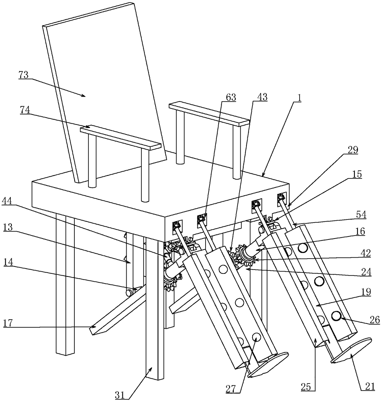
[0036] Embodiment one, combined with the attached Figure 1-10 , a novel orthopedic surgery care frame, comprising a housing 1, characterized in that the lower end of the housing 1 is covered with a U-shaped plate 2 along the left and right directions, the U-shaped plate 2 is arranged along the length direction of the housing 1, and the U-shaped The opening direction of the plate 2 is set upwards, the lower end of the U-shaped plate 2 is fixedly connected to an L-shaped fixed plate 201, and the lower end of the U-shaped plate 2 is provided with a main shaft 3 vertically rotatably connected to the fixed plate 201, The upper shaft end of the main shaft 3 is not in contact with the bottom end of the U-shaped plate 2, and the lower end extends downward. The main shaft 3 is driven by a driving device 4 fixedly connected to the lower end of the housing 1, and the driving device 4 provides power for the main shaft 3. Input, the top of the main shaft 3 is provided with a vertical driv...
Embodiment 2
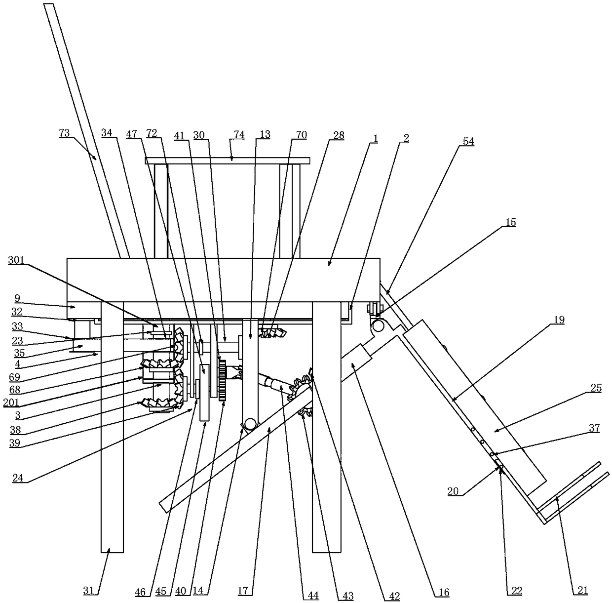
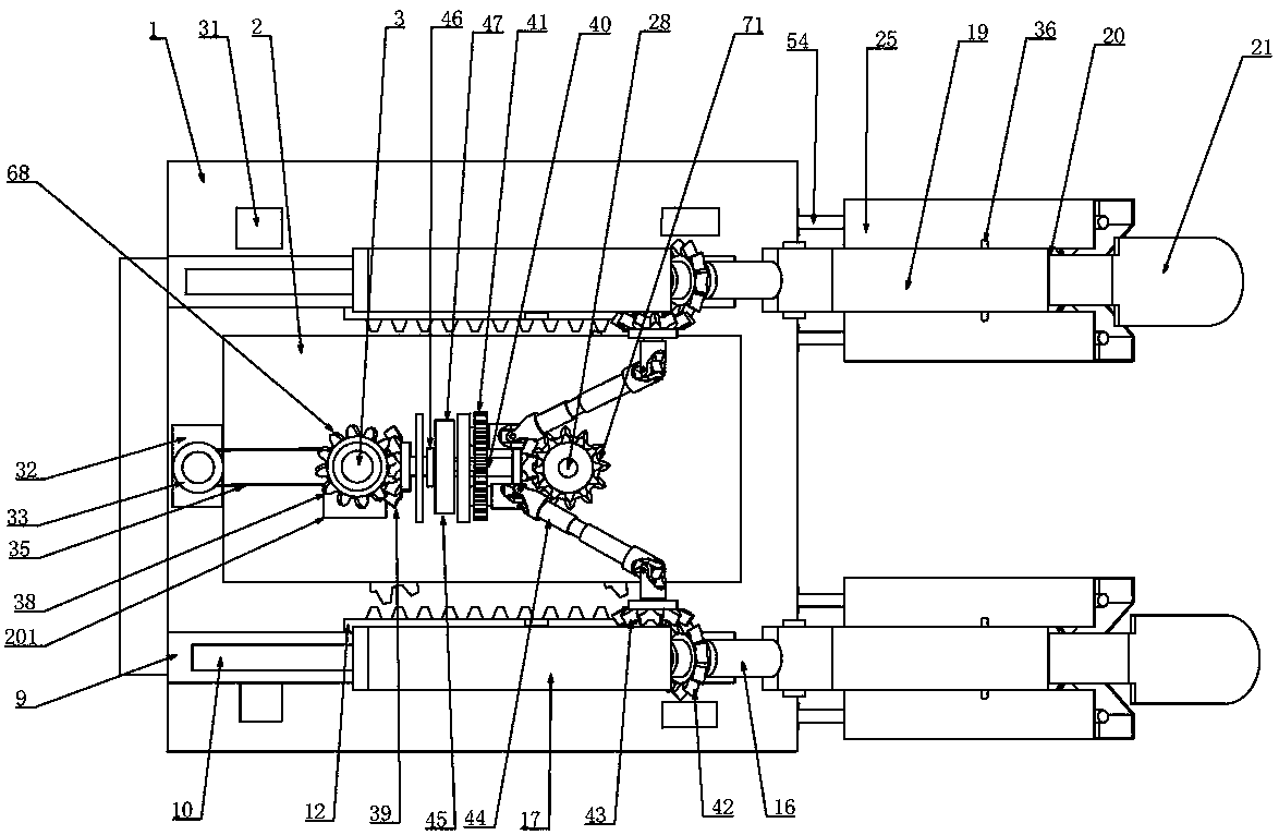
[0043] Embodiment two, on the basis of embodiment one, in conjunction with the attached Figure 1-10 , the drive device 4 includes a drive motor 32 connected to the lower end of the housing 1, the output shaft of the drive motor 32 is coaxially connected to a first pulley 33, and also includes a second pulley 34 coaxially connected to the main shaft 3, A first belt 35 is sheathed between the first pulley 33 and the second pulley 34, and the main shaft 3 transmits power from the drive motor 32 to itself through the first belt 35 to provide power input for itself.
Embodiment 3
[0044] Embodiment three, on the basis of embodiment two, in conjunction with appended Figure 1-10 The adjusting and clamping structure 22 includes elastic pins 36 connected to the front and rear side walls of the pedal 21, and also includes pin holes 37 arranged on the front and rear inner walls of the chute 20 at intervals along the length direction of the chute 20, correspondingly The elastic pin 36 on the corresponding side wall is axially slidably matched with the pin hole 37. When adjustment is required, the head of the elastic pin 36 is pressed into the pin hole 37, and then the pedal 21 and the support plate 19 can be adjusted. Relatively slide, adjust the position of the pedal 21 until it is suitable for the patient's leg length, then cancel the pressing of the elastic pin 36, and the pin hole 37 pops up from the column head, thereby limiting the relative displacement between the pedal 21 and the support plate 19, and playing a role The clamping function is added to a...
PUM
 Abstract
Description
Claims
Application Information
 - R&D
- Intellectual Property
- Life Sciences
- Materials
- Tech Scout
- Unparalleled Data Quality
- Higher Quality Content
- 60% Fewer Hallucinations
Browse by: Latest US Patents, China's latest patents, Technical Efficacy Thesaurus, Application Domain, Technology Topic, Popular Technical Reports.
© 2025 PatSnap. All rights reserved.Legal|Privacy policy|Modern Slavery Act Transparency Statement|Sitemap|About US| Contact US: help@patsnap.com