
Integrated rectifier

A rectifier, controller technology

Inactive Publication Date: 2018-11-16
深圳市百欧森软件技术有限公司
View PDF8 Cites 0 Cited by
  • Summary
  • Abstract
  • Description
  • Claims
  • Application Information

AI Technical Summary

Problems solved by technology

Traditional rectifiers can be made of vacuum tubes, ignition tubes, solid-state silicon semiconductor diodes, mercury arcs, etc., the simplest of which is a half-wave rectifier realized by a diode, and only one rectifier diode can be used to realize the AC-DC conversion function, but The disadvantage is that the output DC voltage is low, the ripple is large, and because the DC flows through the secondary winding of the transformer, the ratio of the volt-ampere value of the rectifier transformer to the DC power is large
The second most commonly used is the bridge rectifier, which is composed of four diodes. Its disadvantage is that it has a single function and low intelligence.

Method used


Image

  • Integrated rectifier
  • Integrated rectifier

Examples


Embodiment 1

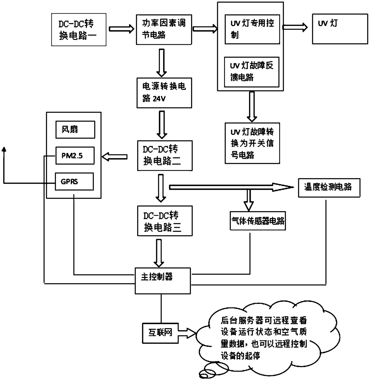
[0020] Embodiment 1: An integrated rectifier, including DC-DC conversion circuit 1, power factor adjustment circuit, power conversion circuit, DC-DC conversion circuit 2, DC-DC conversion circuit 3, main controller, gas sensor circuit, temperature detection circuit, fan and UV lamp dedicated controller, the DC-DC conversion circuit is connected to the power factor adjustment circuit, the power factor adjustment circuit is also connected to the power conversion circuit and the UV lamp dedicated controller respectively, and the power conversion circuit is also connected to the DC-DC conversion circuit Circuit 2, DC-DC conversion circuit 2 is also connected to DC-DC conversion circuit 3, gas sensor circuit, temperature detection circuit and fan, DC-DC conversion circuit 3 is also connected to the main controller, and the main controller is also connected to the gas sensor circuit , Temperature detection circuit and fan, UV lamp dedicated controller connected to UV lamp.

Embodiment 2

[0021] Embodiment 2: An integrated rectifier, including DC-DC conversion circuit 1, power factor adjustment circuit, power conversion circuit, DC-DC conversion circuit 2, DC-DC conversion circuit 3, main controller, gas sensor circuit, temperature detection circuit, fan and UV lamp dedicated controller, the DC-DC conversion circuit is connected to the power factor adjustment circuit, the power factor adjustment circuit is also connected to the power conversion circuit and the UV lamp dedicated controller respectively, and the power conversion circuit is also connected to the DC-DC conversion circuit Circuit 2, DC-DC conversion circuit 2 is also connected to DC-DC conversion circuit 3, gas sensor circuit, temperature detection circuit and fan, DC-DC conversion circuit 3 is also connected to the main controller, and the main controller is also connected to the gas sensor circuit , Temperature detection circuit and fan, UV lamp dedicated controller connected to UV lamp.

[0022] ...


PUM


Abstract

The invention discloses an integrated rectifier comprising a DC-DC conversion circuit I, a power factor adjustment circuit, a power supply conversion circuit, a DC-DC conversion circuit II, a DC-DC conversion circuit III, a main controller, a gas sensor circuit, a temperature detection circuit, a fan and a special-purpose UV lamp controller. The DC-DC conversion circuit I is connected with the power factor adjustment circuit connected with the power supply conversion circuit and the special-purpose UV lamp controller. The integrated rectifier is composed of the DC-DC conversion circuit I, thepower factor adjustment circuit, the power supply conversion circuit, the DC-DC conversion circuit II, the DC-DC conversion circuit III, the main controller, the gas sensor circuit, the temperature detection circuit, the fan and the special-purpose UV lamp controller. The DC-DC conversion circuit I is connected with the power factor adjustment circuit connected with the power supply conversion circuit and the special-purpose UV lamp controller.

Description

technical field [0001] The invention relates to a rectifier, in particular to an integrated rectifier. Background technique [0002] A rectifier (English: rectifier) ​​is a device that converts alternating current into direct current. It can be used for power supply and detection of radio signals. Traditional rectifiers can be made of vacuum tubes, ignition tubes, solid-state silicon semiconductor diodes, mercury arcs, etc., the simplest of which is a half-wave rectifier realized by a diode, and only one rectifier diode can be used to realize the AC-DC conversion function, but The disadvantage is that the output DC voltage is low, the ripple is large, and because the DC flows through the secondary winding of the transformer, the ratio of the volt-ampere value of the rectifier transformer to the DC power is large. The second most commonly used is the bridge rectifier, which is composed of four diodes. Its disadvantage is that it has a single function and low intelligence. ...

Claims


Application Information

Patent Timeline
IPC IPC(8): H05B41/282H05B41/285
CPCH05B41/282H05B41/2851H05B41/2855
Inventor 罗威钟林芝王钢强
Owner 深圳市百欧森软件技术有限公司
Learn More