
Modularization storage rack

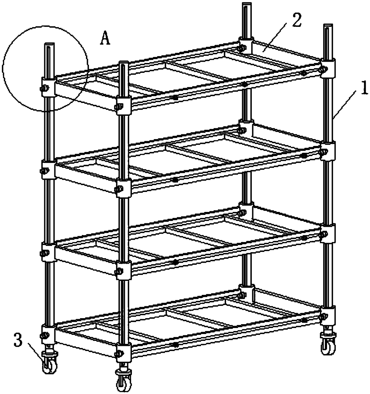
A modular and shelf technology, which is applied in the field of shelf applications and modular shelves, can solve the problems of low cargo capacity, poor stability, and cargo drop, and achieve the effects of convenient operation, universality, and drop prevention

Pending Publication Date: 2018-11-16
江苏金牡蛎金属有限公司
View PDF0 Cites 2 Cited by
  • Summary
  • Abstract
  • Description
  • Claims
  • Application Information

AI Technical Summary

Problems solved by technology

[0004] The purpose of the present invention is to solve the problem that existing shelves have low capacity for goods and can only hold goods of a certain height. When moving the shelf, the goods are easy to fall from the shelf, and the problem of poor stability is to provide a modular shelf

Method used


Image

  • Modularization storage rack
  • Modularization storage rack
  • Modularization storage rack

Examples


Embodiment 1

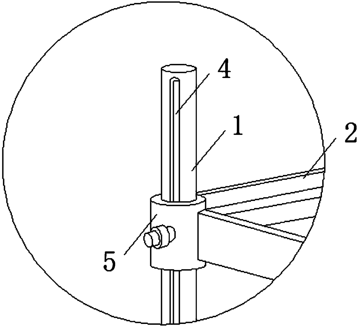
[0022] see Figure 1-6 As shown, the modularized shelf includes a supporting column 1, a pallet 2 and a roller 3, and the four corners of the pallet 2 are installed with supporting columns 1, and four supporting columns 1 are provided with four pallets 2, Rollers 3 are installed at the bottom of the four supporting columns 1, through which the operator can move the shelf. The four supporting columns 1 are all provided with vertical chute 4, and the four corners of the four pallets 2 are provided with socket rings. 5. Both ends of the four pallets 2 are provided with longitudinal baffles 14, both sides of the four pallets 2 are provided with horizontal baffles 10, two horizontal baffles 10 are provided with horizontal chute 11, two Three sliding brackets 13 are stuck between the horizontal chute 11, and the operator slides the hanging posts 15 on the sliding bracket 13 back and forth in the horizontal chute 11, so that the cargo bar 17 on the sliding bracket 13 can carry out th...

Embodiment 2

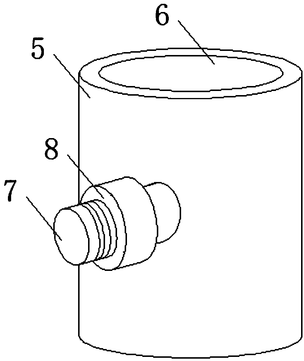
[0024] In addition, please continue to Figure 1-6 As shown, the difference between it and the above-mentioned embodiment is that: the insides of the four sleeve rings 5 ​​are provided with through grooves 6 that match the supporting columns 1, and the four sleeve rings 5 ​​are all equipped with sliding columns 7. By sliding the sliding column 7 up and down in the vertical chute 4, the installation height of the sleeve ring 5 is changed, thereby changing and adjusting the working height of the four pallets 2, which is convenient for the operator to load goods into the pallet 2, and The four sleeve rings 5 ​​are all connected to the inside of the longitudinal chute 4 through the sliding column 7, and the connection between the sliding column 7 and the sleeve ring 5 is installed with a first fixed coil 8, by screwing the first fixed coil 8, The sleeve ring 5 is connected more closely with the supporting column 1 to ensure that the pallet is more stable when loading goods, and th...


PUM


Abstract

The invention discloses a modularization storage rack which comprises a supporting connecting column, pallets, a roller, a longitudinal sliding groove, a sleeving ring, a through groove, a sliding column, a first fixing coil, a thread, a transverse baffle, a transverse sliding groove, a loading groove, a sliding stop frame, a longitudinal baffle, a hanging column, a second fixing coil and a goodsstop strip. The modularization storage rack has the advantages that by vertically sliding the sliding column in the longitudinal sliding groove, the installing height of the sleeving ring is changed,goods can be loaded into the pallets by an operator conveniently, the operator can adjust the using distance between the four pallets according to the loading requirement for loading goods of different heights, and it is ensured that the storage rack can load goods of different heights. By sliding the hanging column on a sliding stop frame back and forth inside the transverse sliding groove, the goods stop strip on the sliding stop frame clamps and fixes the goods, after sliding regulation is completed, the hanging column and the transverse baffle are fixedly connected by screwing the second fixing coil, it is ensured that the goods of different widths can more stable and form when being moved, and falling is avoided.

Description

technical field [0001] The invention relates to a shelf, in particular to a modular shelf, and belongs to the technical field of shelf application. Background technique [0002] With the rapid development of people's living standards, more and more shelves are used in factories. The main function of shelves is to store the goods produced and processed by the factory, so as to facilitate the unified management of the goods by operators. [0003] The current shelves still have many shortcomings. The existing shelves have a low capacity for goods and can only hold goods of a certain height. The width between the pallets on the shelves cannot be adjusted to match the height of the goods, and the flexibility is poor. And when people move the shelves, the goods are easy to fall from the shelves, and the stability is poor. Contents of the invention [0004] The purpose of the present invention is to solve the problem that existing shelves have low capacity for goods and can only...

Claims


Application Information

Patent Timeline
IPC IPC(8): B25H3/04
CPCB25H3/04
Inventor 金雪荣邵惠新
Owner 江苏金牡蛎金属有限公司
Learn More