
Pipeline system of LNG double-gun filling machine

A pipeline system and gas filling pipe technology, applied in pipeline systems, mechanical equipment, gas/liquid distribution and storage, etc., can solve problems such as crowding of gas filling machine components, inaccurate measurement of mass flow meters, and shortening the service life of pumps, etc. Achieve the effect of facilitating assembly and post-maintenance, saving cost and space, and reducing overall costs

Inactive Publication Date: 2018-11-13
JEREH OIL & GAS ENG
View PDF8 Cites 4 Cited by
  • Summary
  • Abstract
  • Description
  • Claims
  • Application Information

AI Technical Summary

Problems solved by technology

[0003] If the small cycle of gun I ends, the gas filling operation will be carried out and when gun II is in the standby state, the pump will stop for a short time, and the frequent start and stop of the pump will reduce the service life of the pump;
[0004] Secondly, due to the gasification of LNG in the pipeline, it is easy to cause gas and liquid mixing, which leads to inaccurate measurement of the mass flow meter;
[0005] The process flow is complicated, there are many parts, and the pipeline arrangement is difficult. On the one hand, it increases the cost of the double-gun gas dispenser; on the other hand, it causes the internal parts of the gas dispenser to be crowded, which brings difficulties to subsequent assembly and maintenance.

Method used


Image

  • Pipeline system of LNG double-gun filling machine
  • Pipeline system of LNG double-gun filling machine
  • Pipeline system of LNG double-gun filling machine

Examples


Embodiment Construction

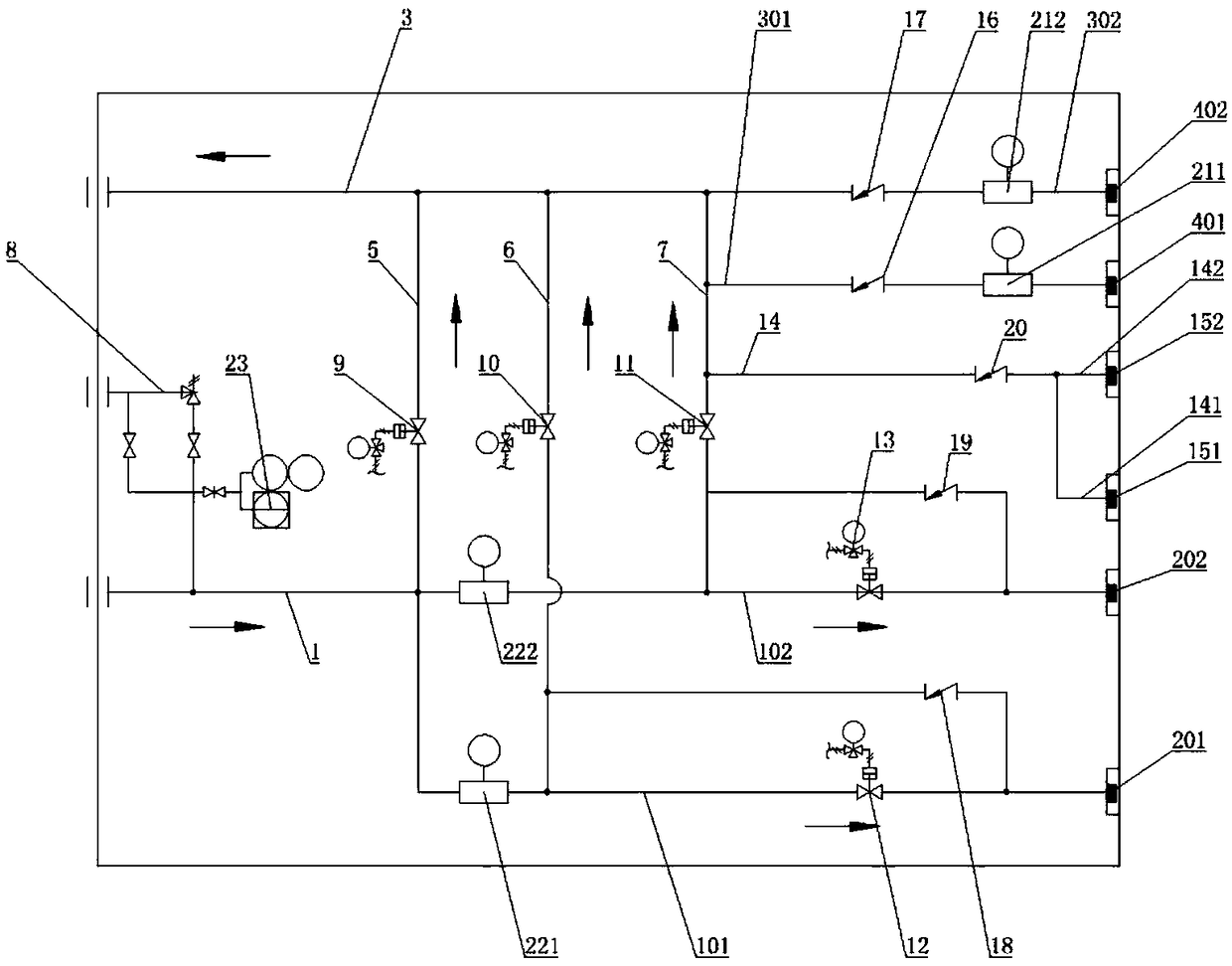
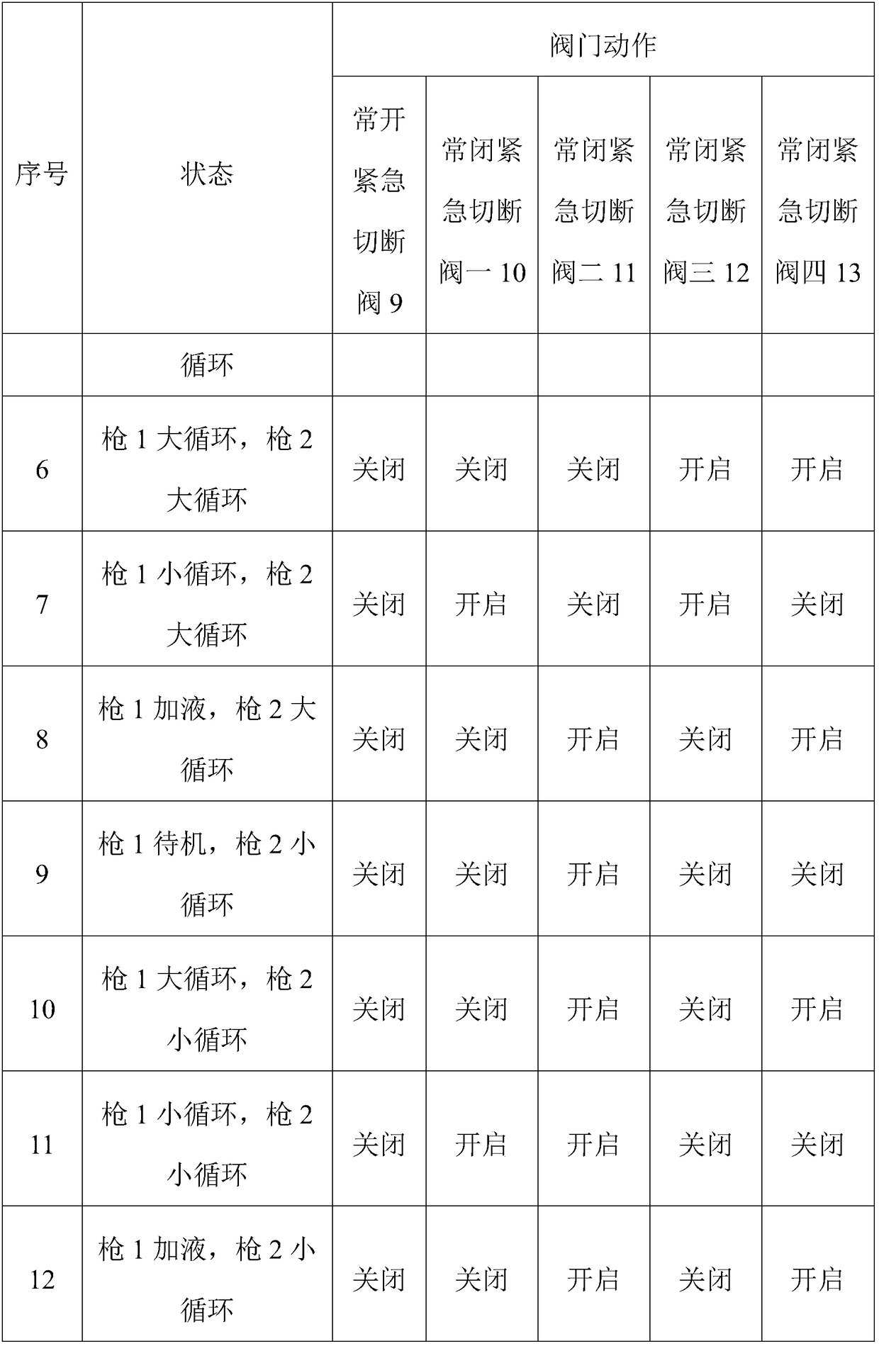
[0023] Such as figure 1 As shown, the direction of the arrow in the figure is the direction of fluid flow when the valve is opened. A pipeline system for LNG double gun filling machine, including gas filling pipeline 1 and gas return pipeline 3, gas filling pipeline 1 includes gas filling pipeline 1 101 and gas filling pipeline 2 102 respectively connected to gas filling gun 1 201 and gas filling gun Two 202, the air return pipeline 3 includes the air return pipeline 1 301 and the air return pipeline 2 302 respectively connected to the air return gun 1 401 and the air return gun 2 402, the system also includes the standby pipeline 5, the small circulation pipeline 1 6, and the small circulation pipe Road 2 7 and safety valve pipeline 8, the safety valve pipeline 8 is connected to the gas filling pipeline 1, a pressure sensor 23 is provided in the safety valve pipeline 8 to monitor the pressure, and the standby pipeline 5 is provided with a normally open emergency shut-off valv...


PUM


Abstract

The invention provides a pipeline system of an LNG double-gun filling machine. The pipeline system comprises a gas filling pipeline and a gas return pipeline, wherein the gas filling pipeline comprises a gas filling pipeline I and a gas filling pipeline II, wherein the gas filling pipeline I and the gas filling pipeline II are connected with a gas filling gun I and a gas filling gun II respectively, and the gas return pipeline comprises a gas return pipeline I and a gas return pipeline II, wherein the gas return pipeline I and the gas return pipeline II are connected with a gas return gun I and a gas return gun II respectively; and the pipeline system further comprises a standby pipeline, a small circulation pipeline I, a small circulation pipeline II and a safety valve pipeline, wherein the safety valve pipeline is connected with the gas filling pipeline, the standby pipeline is provided with a normally opening emergency cut-off valve which is connected with the gas filling pipeline and the gas return pipeline, the small circulation pipeline I is connected with the gas filling pipeline I and the gas return pipeline, and the small circulation pipeline II is connected with the gas filling pipeline II and the gas return pipeline. According to the pipeline system of the LNG double-gun filling machine, the metering precision can be greatly improved, moreover, the structure is simpler, the number of parts is reduced, the assembly and the later maintenance of the gas filling machine are facilitated, and the overall cost is reduced.

Description

technical field [0001] The invention relates to the field of LNG double-gun refilling, in particular to a pipeline system of an LNG double-lance refueling machine. Background technique [0002] At present, a cryogenic submersible pump is usually equipped with two single-gun LNG dispensers or a double-gun LNG dispenser. With the increasing demand for LNG filling volume in the market, the filling station is required The floor area is smaller, and the single-machine double-gun LNG dispenser is more and more popular in the market. On the market, the design idea of ​​the process flow of the double-gun LNG dispenser is to connect the process flow of two single-lance LNG dispensers in parallel. At the same time, due to the limited internal space of the double-lance LNG dispenser, this will easily lead to the following problems: [0003] If the small cycle of gun I ends, the gas filling operation will be carried out and when gun II is in the standby state, the pump will stop for a ...

Claims


Application Information

Patent Timeline
IPC IPC(8): F17D1/08F17D3/01F17D3/18
CPCF17D1/082F17D3/01F17D3/18
Inventor 张先进李国富刘政郭志彬王军孟繁荣
Owner JEREH OIL & GAS ENG
Learn More