Aeroengine rotor part turning device

An aero-engine and flipping device technology, applied in the field of aero-engines, can solve problems such as inconvenient use, complicated operation steps, and low efficiency, and achieve the effects of improved stability, convenient and fast use, and high implementability

Active Publication Date: 2018-11-13
AECC COMML AIRCRAFT ENGINE CO LTD
View PDF5 Cites 1 Cited by
  • Summary
  • Abstract
  • Description
  • Claims
  • Application Information

AI Technical Summary

Problems solved by technology

[0003] The existing turning device of the engine usually consists of two sets of parts, the operation steps are complicated and the efficiency is low
Moreover, the existing fan unit turning device cannot adjust the position of the center of gravity of the lifting point, or the position of the center of gravity needs to be adjusted before assembly, which is very inconvenient to use, and the lifting stability is not high

Method used


Image

  • Aeroengine rotor part turning device
  • Aeroengine rotor part turning device
  • Aeroengine rotor part turning device

Examples


Embodiment Construction

[0025] The technical solutions of the present invention will be described in further detail below with reference to the accompanying drawings and embodiments.

[0026] The specific embodiments of the present invention are for the convenience of further description of the concept of the present invention, the technical problems to be solved, the technical features constituting the technical solution and the technical effects brought about. It should be noted that the description of these embodiments does not constitute a limitation of the present invention. In addition, the technical features involved in the embodiments of the present invention described below may be combined with each other as long as they do not conflict with each other.

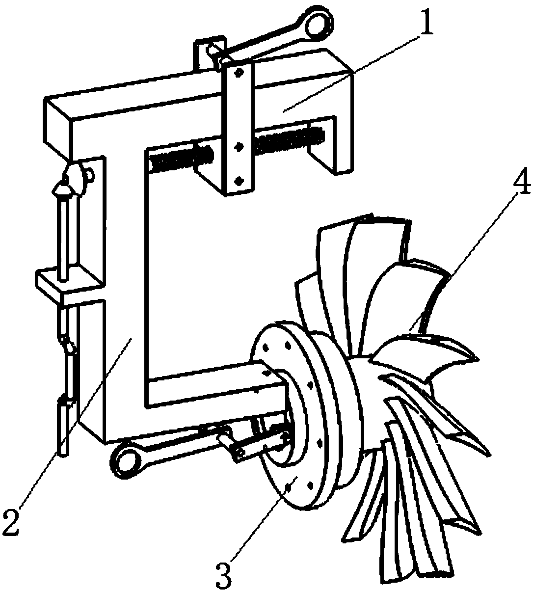
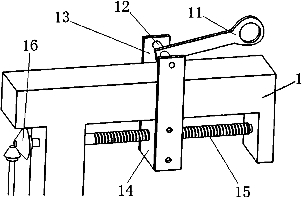
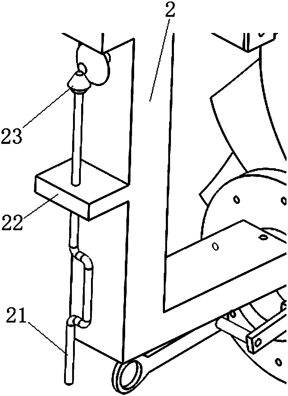
[0027] In a schematic embodiment of the aero-engine rotor turning device of the present invention, combined with Figure 1 to Figure 5 As shown, the aero-engine rotor part turning device is used to turn over the rotor part 4 to be turned o...


PUM


Abstract

The invention relates to an aeroengine rotor part turning device used for turning over a to-be-turned rotor part. The device includes an adjustable lifting arm and a fixed lifting arm. The top of thefixed lifting arm is fixedly connected to the adjustable lifting arm. The bottom of the fixed lifting arm is used for connecting to the to-be-turned rotor part. A first lifting rod is arranged on theadjustable lifting arm. The first lifting rod can move relative to the adjustable lifting arm, and so a lifting position is adjustable. The aeroengine rotor part turning device is provided with the movable first lifting rod on the adjustable lifting arm, and so the lifting position can be changed in real time during lifting so as to adjust the center of gravity. Therefore, the stability in the assembly and turnover process is improved, the use of the device is convenient and fast, and the practicability is high.

Description

technical field [0001] The invention relates to the technical field of aero-engines, in particular to an overturning device for an aero-engine rotor. Background technique [0002] The complete aircraft engine is usually placed with the axis parallel to the ground. Therefore, when installing or removing the fan at the front of the engine, the rotation axis of the fan is parallel to the ground. After disassembly, in order to facilitate the placement of the fan, the fan should be turned 90 degrees. The fan also needs to be rotated 90 degrees during installation. [0003] The existing turning device of the engine usually consists of two sets of parts, the operation steps are complicated, and the efficiency is low. Moreover, the existing fan unit turning device cannot adjust the position of the center of gravity of the lifting point, or the position of the center of gravity needs to be adjusted before assembly, which is very inconvenient to use, and the lifting stability is not ...

Claims


Application Information

Patent Timeline
Patent Type & Authority Applications(China)
IPC IPC(8): B66C1/22
CPCB66C1/22
Inventor 赵岩李琳胡一廷汪俊熙梁霄
Owner AECC COMML AIRCRAFT ENGINE CO LTD
Why Eureka
Try Eureka