
Patsnap Eureka
For R&D, Patsnap Eureka makes reading and utilizing patents & technical documents easy.
Patsnap Eureka AIR
Designed for self-driven R&D workflows. Generate viable solutions, solve complex R&D challenges, empower your innovation with AI.

Patsnap Eureka Materials
Designed for material experts only. Revolutionize your material R&D, from search, analyze, to developing new materials.

TechResearch
Generate reliable direction feasibility study reports for your R&D in just a few steps.

TechSeek
Discover and master advanced knowledge NOW. Basics, ideas, possibilities, all at once.

TechMind
As an expert in R&D Theories, TechMind can generates customized viable solutions instantly.

TechRisk
Analyze your overall solution with one click, know your potential R&D risks in advance.

TechMonitor
Get weekly tech updates, stay abreast of the latest tech innovations and key insights.
Transmission device for horizontally moving translation plate
A technology of a transmission device and a translation plate, which is used in transportation and packaging, conveyors, escalators, etc., can solve the problem of not being able to continuously change rails for multiple moving plates, and achieve a fixed and simple structure, less translation plates, and maintenance costs. low effect
- Summary
- Abstract
- Description
- Claims
- Application Information
AI Technical Summary
Problems solved by technology
Method used
Image

Examples
Embodiment 1
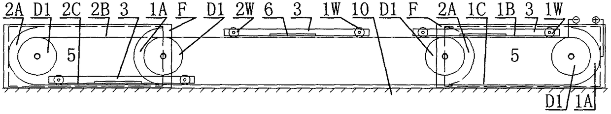
[0111] Embodiment 1: refer to Figure 1 to Figure 10 . The power unit (M) is an electric motor. Outer rails (1) and inner rails (2) are installed side by side on both sides of the transmission device, the outer rails (1) on both sides are outside the inner rails (2), and the outer semicircular arc rails (1A) at both ends of the outer rail (1) are connected The outer rail (1B) and the outer rail (1C), the outer semicircle arc rail (1A) is outside the outer rail (1B) and the outer rail (1C), and the inner semicircle arc rail (2A) at both ends of the inner rail (2) connects the inner Rail (2B) and inner rail (2C), inner semicircle arc rail (2A) outside inner rail (2B) and inner rail (2C), outer semicircle arc at one end of outer rail (1) and inner rail (2) The rail (1A) protrudes from the front inner semicircle arc rail (2A), and the inner semicircle arc rail (2A) at the other end of the outer rail (1) and the inner rail (2) protrudes from the front outer semicircle arc rail (1...
Embodiment 2
[0114] Embodiment 2: refer to Figure 11 , Figure 12 . The outer semi-circular arc rail (1A) and the inner semi-circular arc rail (2A) at one end of the outer rail (1) and the inner rail (2) are mounted on a platform of the stairs (9A), and the outer rail (1) and the inner rail (2) The inner semicircle rail (2A) and the outer semicircle rail (1A) at the other end are installed on the other platform of the stairs (9A). In order to reduce the complexity of the view, a translation plate (3) is translated between the outer rail (1) and the inner The rails (2) are in different positions. Wherein when the translation plate (3) moves the outer rail (1C) and the inner rail (2C) closest to the steps of the stairs (9A), the translation plate (3) is not loaded and can be tilted. All the other are identical with embodiment 1.
[0115] The height of the high rail and the low rail of the present invention is smaller than the vertical surface of the stair steps, and can be additionally ...
Embodiment 3
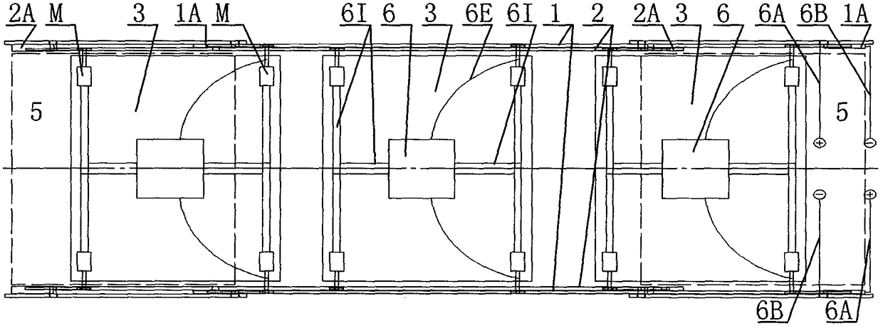
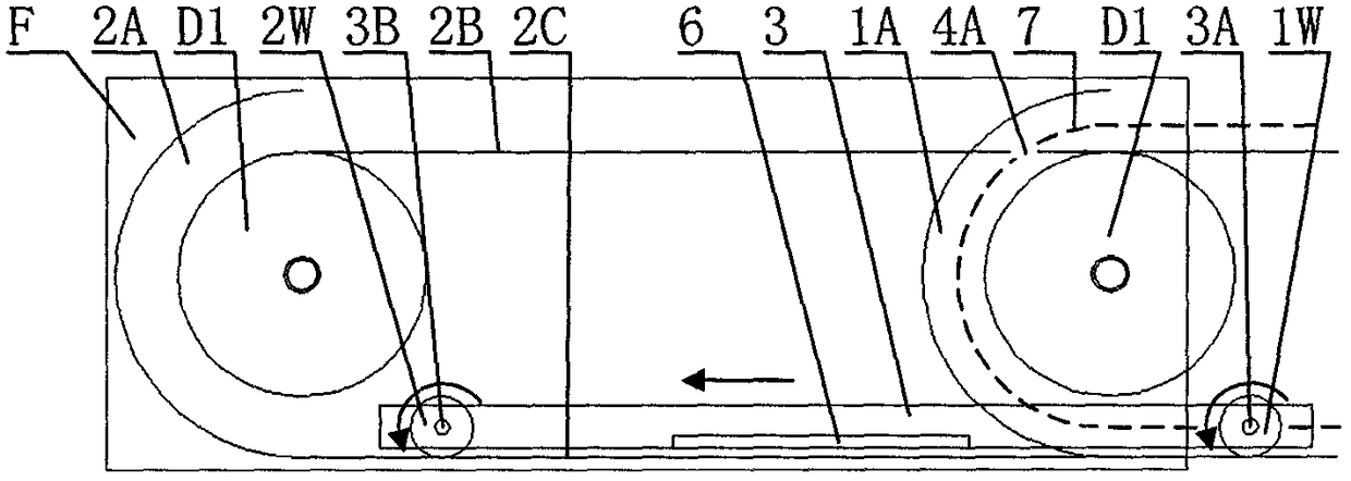
[0116] Embodiment 3: refer to Figure 13 to Figure 26 . The high end and low end of the right outer semicircle arc rail (1A) are connected to the outer rail (1B) and outer rail (1C), and the high end and low end of the right inner semicircle arc rail (2A) are connected to the inner rail (2B) and inner rail (2C). The high end and low end of the left outer semicircle arc rail (1A) are connected to the outer rail (1C) and outer rail (1B), and the high end and low end of the left inner semicircle arc rail (2A) are connected to the inner rail (2C), inner rail (2B). It is connected as multilayer outer rail (1) and inner rail (2). A plurality of conveyor belts (8) are arranged longitudinally. refer to Figure 15 to Figure 26 . The section (4A) is equipped with section rails (4C) at the front and back, the middle of the plate (P) is connected with the inner shaft (3B), and the front and rear of the plate (P) are equipped with section wheels (4W). )move. All the other are ident...
PUM
 Abstract
Description
Claims
Application Information
 - R&D Engineer
- R&D Manager
- IP Professional
- Industry Leading Data Capabilities
- Powerful AI technology
- Patent DNA Extraction
Browse by: Latest US Patents, China's latest patents, Technical Efficacy Thesaurus, Application Domain, Technology Topic, Popular Technical Reports.
© 2024 PatSnap. All rights reserved.Legal|Privacy policy|Modern Slavery Act Transparency Statement|Sitemap|About US| Contact US: help@patsnap.com