
Unmanned aerial vehicle and machine arm assembly and rotating shaft mechanism thereof

A shaft and arm technology, applied in the field of aircraft, can solve problems such as unexpected movement and unmanned aerial vehicles failing to achieve effective and accurate attitude flight.

Active Publication Date: 2018-11-13
SHENZHEN AUTEL INTELLIGENT AVIATION TECH CO LTD
View PDF5 Cites 2 Cited by
  • Summary
  • Abstract
  • Description
  • Claims
  • Application Information

AI Technical Summary

Problems solved by technology

[0004] The purpose of the embodiments of the present invention is to provide an unmanned aerial vehicle and its arm assembly and shaft mechanism, so as to solve the problem that the unmanned aerial vehicle in the prior art is easy to accidentally move to The folded position when it is in the non-working state makes the unmanned aerial vehicle unable to achieve the technical problem of flying in an effective and accurate attitude

Method used


Image

  • Unmanned aerial vehicle and machine arm assembly and rotating shaft mechanism thereof
  • Unmanned aerial vehicle and machine arm assembly and rotating shaft mechanism thereof
  • Unmanned aerial vehicle and machine arm assembly and rotating shaft mechanism thereof

Examples


Embodiment Construction

[0058] In order to facilitate the understanding of the present invention, the present invention will be described in more detail below in conjunction with the accompanying drawings and specific embodiments. It should be noted that when an element is said to be "fixed" to another element, it may be directly on the other element, or there may be one or more intervening elements therebetween. When an element is referred to as being "connected to" another element, it can be directly connected to the other element or one or more intervening elements may be present therebetween. The terms "vertical", "horizontal", "left", "right", "inner", "outer" and similar expressions are used in this specification for the purpose of description only.

[0059] Unless otherwise defined, all technical and scientific terms used in this specification have the same meaning as commonly understood by one of ordinary skill in the technical field of the invention. Terms used in the description of the pre...


PUM


Abstract

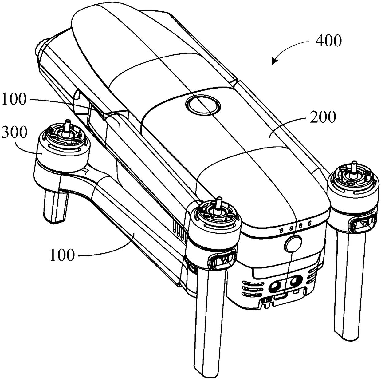
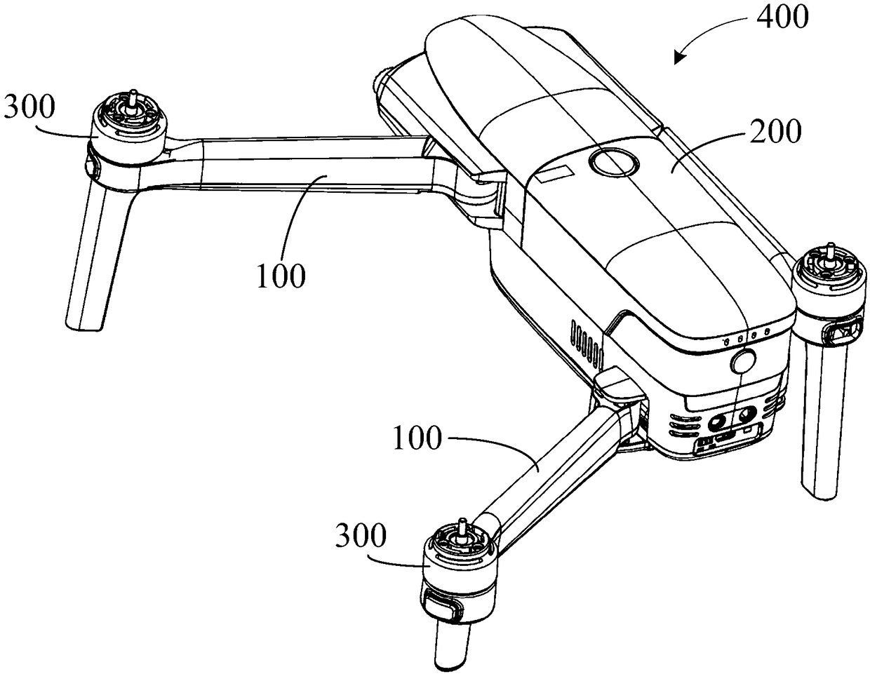
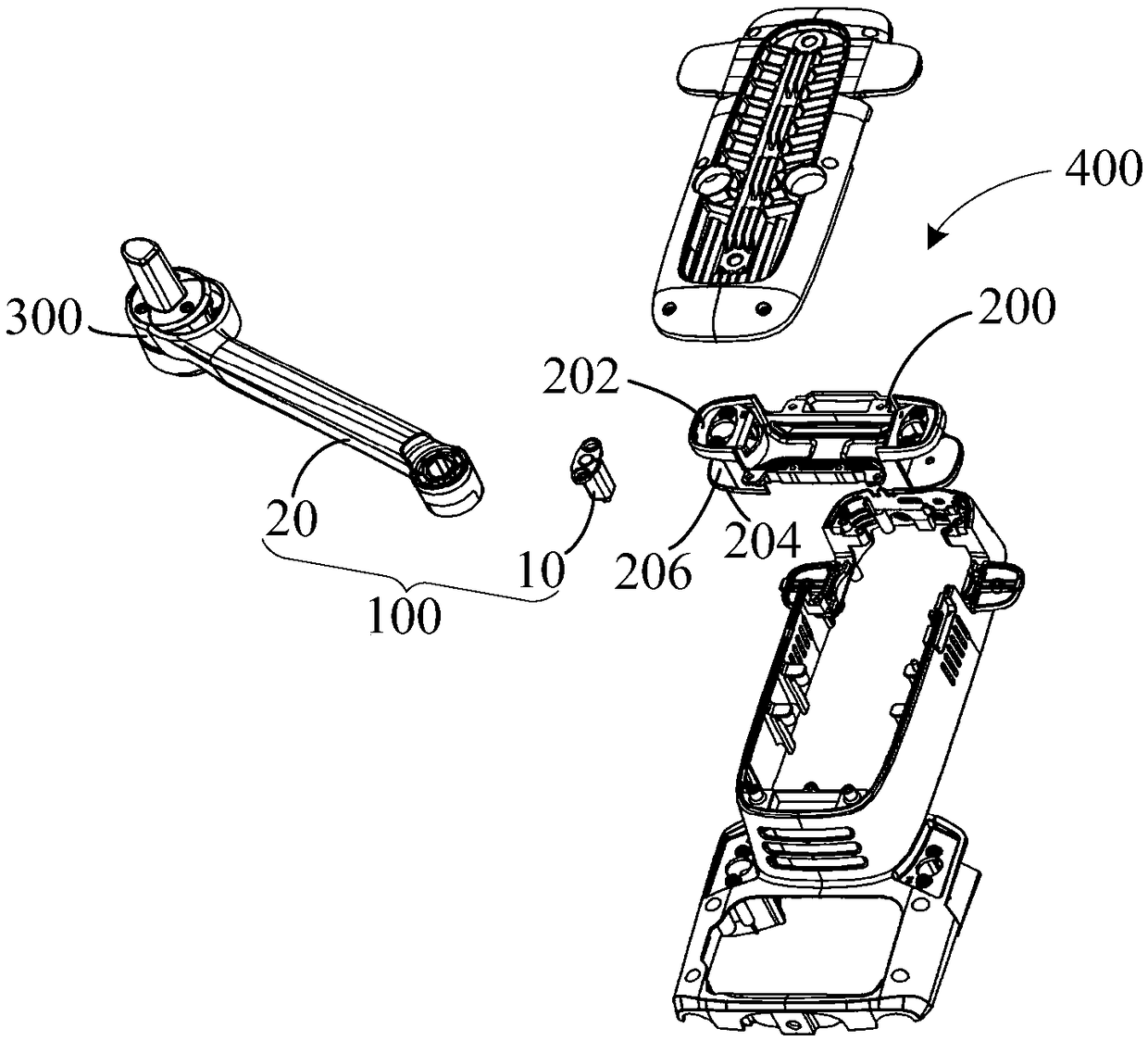
The invention provides an unmanned aerial vehicle and a machine arm assembly and a rotating shaft mechanism thereof. The rotating shaft mechanism comprises a central shaft, a fixed seat, a shaft sleeve capable of rotating relative to the central shaft, a rotating member which is at least partially accommodated in the shaft sleeve and an elastic member accommodated in the shaft sleeve. The fixed seat, the shaft sleeve, the rotating member and the elastic member are all arranged on the central shaft in a sleeving mode. The fixed seat is connected with the rotating member in an abutting mode, atleast one of the fixed seat and the rotating member is provided with a cam curved surface, and the cam curved surface enables the rotating member to move along the axis of the central shaft when the rotating member is driven to rotate by the shaft sleeve. The shape of the cam curved surface enables the thrust of the shaft sleeve driving the rotating member to rotate in the first rotating directionto be greater than the thrust of the shaft sleeve driving the rotating member to rotate in the opposite second rotating direction. With the structure, the problem that machine arms connected to the unmanned aerial vehicle through the rotating shaft mechanism accidentally move in the first rotating direction to the folded position when the machine arms are in the non-working state from an unfoldedposition when the machine arms are in the working state due to an undesired external force is effectively solved.

Description

【Technical field】 [0001] The invention relates to the field of aircraft, in particular to an unmanned aircraft, an arm assembly and a rotating shaft mechanism thereof. 【Background technique】 [0002] Unmanned aerial vehicle, referred to as unmanned aerial vehicle (UAV), is a new concept equipment in rapid development, which has the advantages of flexible maneuvering, quick response, unmanned driving, and low operation requirements. The unmanned aerial vehicle is equipped with various types of sensors or camera devices through the gimbal, which can realize real-time image transmission and detection of high-risk areas. It is a powerful supplement to satellite remote sensing and traditional aerial remote sensing. [0003] The arm of a common unmanned aerial vehicle is connected to the fuselage through a rotating shaft mechanism. When the arm turns to one side, it is in a folded position, and the other side is in an unfolded position (also called a working state), and the rotati...

Claims


Application Information

Patent Timeline
Patent Type & Authority Applications(China)
IPC IPC(8): B64C1/30B64C27/08
CPCB64C1/30B64C27/08B64U10/10
Inventor 梁智颖
Owner SHENZHEN AUTEL INTELLIGENT AVIATION TECH CO LTD
Learn More